SYNCHRO EXCITE Class & Trend: Service & maintenance manual - rev. 2.0
Page 7.37
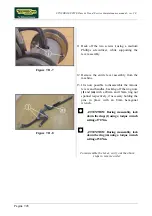
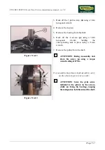
Figure 7.14-11
3.
Back off the 2 grub screws
(n)
using a 3mm
hexagonal wrench.
4.
Remove the key
(o)
.
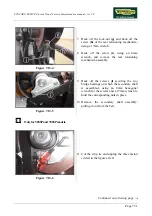
5.
Remove the bearing from the shaft.
6.
Back off the 4 screws
(p)
using a 5mm
hexagonal wrench, holding the
corresponding nuts in place using a 13mm
wrench.
7.
Remove the pulley from the shaft.
ATTENTION: During reassembly, lock
down the screws (p) using a torque
wrench setting of 22 Nm.
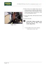
Figure 7.14-12
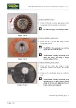
To reassemble the primary shaft assembly, carry
out the above steps in reverse order.
ATTENTION: Screw the grub screws
indicated in the picture by the arrows,
which are fixing the bearings, keeping
them aligned on both the sides of the shaft.
Summary of Contents for Synchro Excite 500
Page 1: ...SERVICE MAINTENANCE MANUAL REV 2 0 ...
Page 2: ......
Page 4: ......
Page 48: ...SYNCHRO EXCITE Class Trend Service maintenance manual rev 2 0 Pagina 4 6 LIBYA DVB T ...
Page 50: ......
Page 201: ......

