SYNCHRO EXCITE Class & Trend: Service & maintenance manual - rev. 2.0
Page 9.27
9.4.3.3.
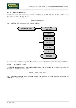
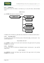
COM.Fault
This is a counter that display the number of errors in serial communication between the upper and
the lower kit. This counter increase each time a communication fault is detected. Scroll using the
+/- keys until the display shows:
COM.FAULT X
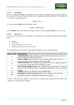
To reset it press
ENTER
, the LED display shows:
RESET COM.FAULT?
press
ENTER
to reset and return to the upper menu level by pressing
CLEAR
for a few seconds.
9.4.3.4.
View Errors
For every error generated by the machine, the error history log records the information in the table
below:
•
Counter
•
Error code
•
Current when the error occurred
•
Distance in km when the error occurred
The correspondence between error codes and descriptions is given in the table below:
Error Code Description
1
OVERHEATING:
this condition occurs when the temperature detected by the
sensor on the circuit board exceeds 90°C.
2
OVERCURRENT:
this condition occurs when the Brake board detects an
excessive amount of current being sent to the winding.
8
OVERVOLTAGE:
this condition occurs when the +12 Vdc voltage goes above
13.7 Vdc (only on the 500, 700, and 700WTV models).
16
SOLENOID OVERHEATING:
this condition occurs when the NTC, connected
in series with the solenoid, detects a temperature higher than 140°C and opens the
circuit.
32
EPROM
: SW error on the Brake board (braking table).
128
REFERENCE VOLTAGE FAULT:
this error condition occurs when the
calibration parameter stored in the Brake board is incorrect.
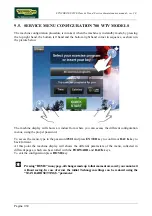
Use the
+
effort level key to advance to the next error, otherwise the message with the details of the
current error will continue to reappear.
Summary of Contents for Synchro Excite 500
Page 1: ...SERVICE MAINTENANCE MANUAL REV 2 0 ...
Page 2: ......
Page 4: ......
Page 48: ...SYNCHRO EXCITE Class Trend Service maintenance manual rev 2 0 Pagina 4 6 LIBYA DVB T ...
Page 50: ......
Page 201: ......


