SYNCHRO EXCITE Class & Trend: Service & maintenance manual - rev. 2.0
Pagina 7.26
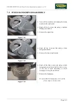
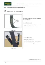
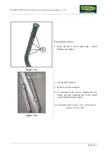
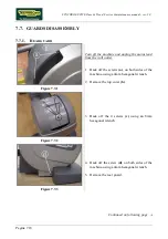
7.11.
PLATFORM LEVER DISASSEMBLY
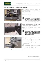
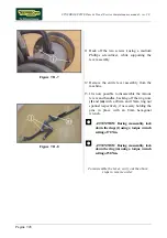
Figure 7.11-1
Carry out the operations described in
paragraph: 7.7.2. “Brake box cover guard” and
7.7.3. “Front guards”.
1.
Remove the cap
(a)
.
ATTENTION: If the screw (1) is backed
off, during reassembly, apply a drop of
Loctite thread compound and lock down
using a torque wrench setting of 44 Nm.
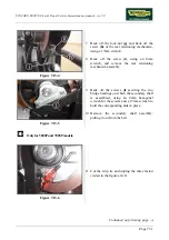
Figure 7.11-2
2.
Back off the nut
(b)
on the lower part of the
lever, using a 17mm hexagonal wrench.
3.
Back off the screw
(c)
, using a 8mm
hexagonal wrench.
ATTENTION: During reassembly, lock
down the screw (c) using a torque wrench
setting of 40 Nm, and lock down nut (b)
using a setting of 30 Nm.
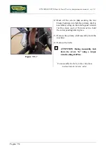
Figure 7.11-3
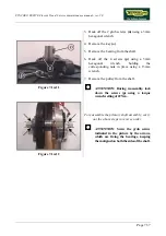
4.
Using a 6mm hexagonal wrench, back off the
6 screws
(d)
securing the bushing assembly
that connects to the upper lever.
5.
Remove the bushing assembly from the
machine frame.
ATTENTION: During reassembly, lock
down the screws (d) using a torque
wrench setting of 38 Nm.
Continued on following page
→
Summary of Contents for Synchro Excite 500
Page 1: ...SERVICE MAINTENANCE MANUAL REV 2 0 ...
Page 2: ......
Page 4: ......
Page 48: ...SYNCHRO EXCITE Class Trend Service maintenance manual rev 2 0 Pagina 4 6 LIBYA DVB T ...
Page 50: ......
Page 201: ......


