TOP 600 XTPRO: Service & Maintenance Manual - rev. 2.0
3. PRINCIPLES OF OPERATION
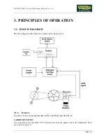
3.1. BLOCK DIAGRAM
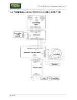
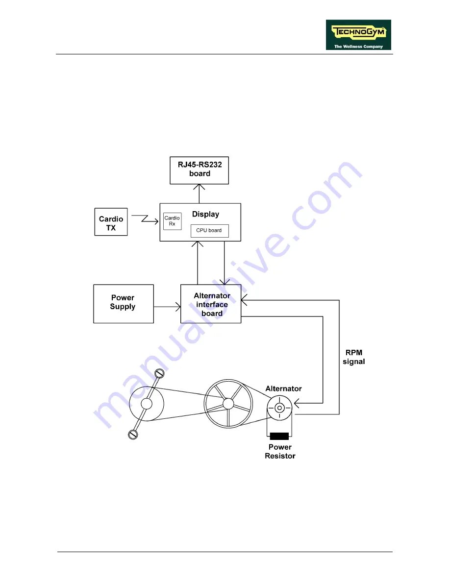
The block diagram of the machine is shown in the figure below:
3.1.1. D
ISPLAY
It consists of various components that will be individually described below:
CARDIO RECEIVER
It is connected to the machine’s CPU board and receives the pulses sent by the transmitter. There
are 2 types of receiver:
Page 3.1
Summary of Contents for Top 600 XTPRO
Page 1: ...SERVICE MAINTENANCE MANUAL REV 2 0...
Page 2: ......
Page 4: ......
Page 8: ...TOP 600 XTPRO Service Maintenance Manual rev 2 0 Page iv Page intentionally left blank...
Page 18: ...TOP 600 XTPRO Service Maintenance Manual rev 2 0 Page 2 8 Page intentionally left blank...
Page 26: ...TOP 600 XTPRO Service Maintenance Manual rev 2 0 Page 4 2 Page intentionally left blank...
Page 58: ...TOP 600 XTPRO Service Maintenance Manual rev 2 0 Page 7 18 Page intentionally left blank...
Page 70: ...TOP 600 XTPRO Service Maintenance Manual rev 2 0 Page 9 6 Page intentionally left blank...
Page 82: ......
Page 83: ...TOP 600 XTPRO Service Maintenance Manual rev 2 0 Page intentionally left blank Page 11 1...
Page 84: ......
Page 93: ......

