TS Enclosure 550 User Manual
Rev. 1.
2
TS-ENC550 - 11
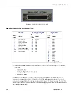
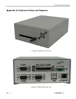
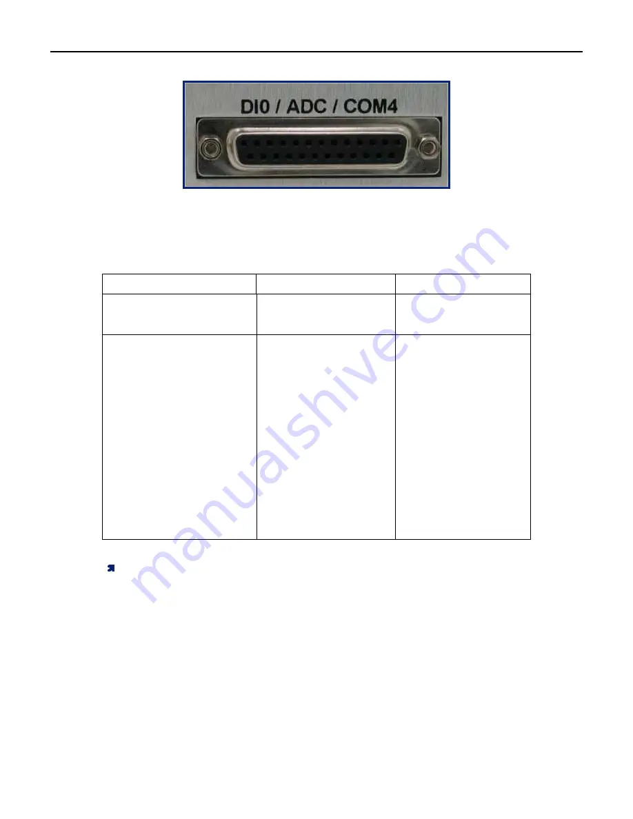
Enclosure TS-ENC550 DI0/ADC/COM4 Port
DIO/ADC/COM4 25-Pin SubD Outs Table
RS-232
Analog to Digital
Digital I/O
25-Pin
SubD
Signal
25-
Pin
SubD
Signal
25-Pin
SubD
Signal
2
2
Transmit data
9
9
Ground
1
1
DIO0
3
3
Receive data
1
1
0
0
AD0
2
2
DIO1
4
4
Request To Send
1
1
1
1
AD1
3
3
DIO2
5
5
Clear To Send
1
1
2
2
AD2
4
4
DIO3
6
6
Data Set Ready
1
1
3
3
AD3
5
5
DIO4
7
7
Ground
2
2
2
2
AD4
6
6
DIO5
8
8
Data Carrier Detect
2
2
3
3
AD5
7
7
DIO6
2
2
0
0
Data Terminal Ready
2
2
4
4
AD6
8
8
DIO7
2
2
2
2
Ring Indicator
2
2
5
5
AD7
1
1
4
4
Ground
1
1
5
5
DIO8
1
1
6
6
DIO9
1
1
7
7
DIO10
1
1
8
8
DIO11
1
1
9
9
DIO12
2
2
0
0
DIO13
2
2
1
1
+5v @ 250 mA
DIO/ADC/COM4: COM4 for the ENC550 can be connected internally to one of three
functions.
•
COM4 RS-232
•
Analog to Digital Converter inputs
•
Digital I/O points
The DIO is a standard feature of all Technologic Systems SBCs. By default the 25-pin
connector is plugged into DIO1. If the ADC or COM4 options are purchased, the 25-pin
connector is plugged into the purchased option. Only one of the headers on the TS-ENC550
power supply board may be connected at one time. Plugging more than one of the headers in
may damage the circuitry.


