background image


IZI Technology Inc

, 3651 Pegasus Dr. Ste. 117 Bakersfield, CA 93308 USA.  

Tel

: (661) 412-3494 -- 

email

sales@izitechnology.com


www.izitechnology.com


Ethernet/IP Tag Client 


Like  in  the  other  protocols  configuration,  the  user  has  to  define  data  transfer  blocks  in  the 
Ethernet/IP Tag Client to transfer a PLC Tag Data to or from the SPX5 internal database.  

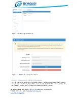
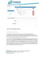
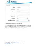
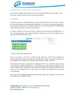
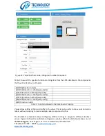
In figure 24 the 

“Protocol Settings”

 section is displayed. These settings identify the Allen Bradley 

PLC that the user wants to access and general communication settings. These are the configuration 
parameters available in this section: 

PLC IP Address:

 This is the IP Address of an Allen Bradley Ethernet interface card on the same chassis 

as the PLC that the user wants to access. 

Processor Slot:

 This is the slot where the PLC resides on the rack. For PLCs with no movable racks 

(like MicroLogix and CompactLogix) 0 must be used. 

Conn. Timeout:

 This is the connection timeout when trying to connect to the specified PLC. 

Msg. Timeout:

 This is the timeout from messages on an open PLC Connection. 

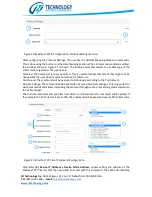
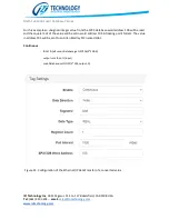
Like  in  the  other  protocols  configuration,  the  user  has  to  define  data  transfer  blocks  in  the 
Ethernet/IP Tag Client to transfer a PLC Tag Data to or from the SPX5 internal database. To create 
transfer blocks the buttons in the Data Mapping section are used. When adding or editing a new 
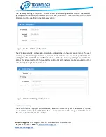
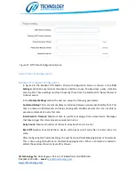
data  transfer  the  Tag  Setting  section  will  show.  This  is  the  detail  of  all  possible  configuration 
parameters in this section: 

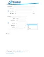
Enable: 

The enable parameter has three options: Disabled: This is used to disable a data transfer 

when the user doesn’t require the command to be executed but doesn’t want to remove it. Enabled: 
The data transfer will be executed continuously. On Data Change: The data transfer will happen only 
when data changes. This option only works on Writes. 

Data Direction:

 Defines if the configured data transfer will be a Read of PLC data or a Write to the 

PLC. 

Tagname:

  This is the name of the tag that the user wants to read or write from the Allen Bradley 

PLC. The tag must be defined as a Controller Tag on the PLC. The format for the tag name follows 
the  standard  format  defined  for  Allen  Bradley  Logix  PLCs.  Examples  of  tag  names  are:  tag, 
tag.element, tag[index], tag[index].element[index].element. 

Data Type:

 This is the type of the element that is read from the PLC. If the specified data type of the 

tag doesn’t match during the execution of the command, the data transfer will fail. 

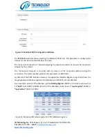
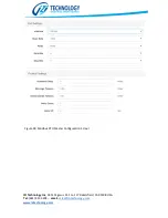
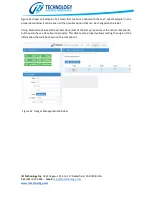
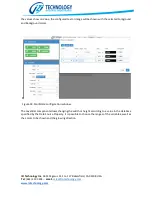
Register Count:

 For accessing tag elements that are not arrays this parameter must be always 1. If 

the accessed element of a tag is an array, then this parameter is the number of elements to be read 
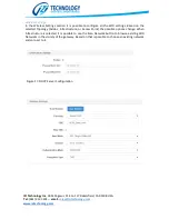
from that array. If for example the user has a Controller Array Tag with the name EXA and the user 
wants to read 20  elements, starting with element 100 up to element 119, then the user will have 
to enter a configuration like shown on Figure 25. 


Summary of Contents for SPX5

Page 1: ...SPX5 INDUSTRIAL GATEWAY User Manual...

Page 2: ...10 Data Base 11 Module Configuration 12 Gateway Name and Description 12 Gateway Security Configuration 12 Ethernet LAN and WiFi WLAN Configuration 13 Network Protocols Configuration 16 Modbus TCP IP...

Page 3: ...i standard By using the friendly WEB based configuration tool the user can configure reads and writes using all the available industrial communication protocols The SPX5 can also be programmed using a...

Page 4: ...Supply Connector The SPX5 can be powered with a 9 to 48 Volts DC power supply and the maximum power consumption is of 5Watts The power supply connector is located on the top side of the gateway and th...

Page 5: ...for reception whereas T and T are used for the transmission pair Serial Ports Configuration Switches The SPX allows configuring Pull Up Pull Down and termination resistors in the RS485 RS422 network T...

Page 6: ...he SPX5 has a 10 100 1000 Mb s capable Ethernet Port This port supports all type of network communications like Ethernet IP and Modbus TCP IP This port is also used for configuring the SPX5 using our...

Page 7: ...transfer is happening on the respective port A solid Rx or TX line indicates a faulty connection on the respective port Typically a solid light is associated with a mismatched polarity of the connecti...

Page 8: ...izitechnology com To restart the unit to factory defaults the reset button must be pressed for 10 seconds At this point the internal configuration will be replaced with the factory default settings T...

Page 9: ...ower supply and the Ethernet port must be connected to the configuration personal computer From the IZI Technology web site download and install the SPX5 Browser This application is only supported in...

Page 10: ...access it through the network For each detected SPX5 on the network the SPX5 Browser will show Gateway Name Serial Number or MAC Address 3 SPX5 Configured IP Address 4 Temporary IP Address 7 and Firm...

Page 11: ...5 Then using another protocol that same information is transferred to a different device The SPX5 also supports writing simple user scripts that allow conversion of data values or executing logic upon...

Page 12: ...ormat and Byte Swapping Table 1 shows all the possible data types Figure 12 SPX5 Database Visualization of the Status Web Page NAME Range Description INT16 DEC 32 768 hasta 32 767 16 bit signed intege...

Page 13: ...d The Items shown on Figure 13 Allow configuring 1 General Gateway Configuration Name and Description 2 Access Security 3 LAN Ethernet Port and WLAN Wireless Interface 4 Network Protocols 5 Scripts Ed...

Page 14: ...nfiguration Screen Figura 13 SPX5 Security Configuration Screen Ethernet LAN and WiFi WLAN Configuration The LAN interface Wired Ethernet is always enabled The user must configure the IP Address netwo...

Page 15: ...ending on the user requirements The user must specify the IP settings IP Address Network Mask and Gateway It s very important that the settings for LAN and WLAN are in different subnets Although a Gat...

Page 16: ...possible to configure all the WiFi settings Based on the selected Topology AdHoc Infrastructure or Access Point the possible options change When Infrastructure is selected it is possible to use the S...

Page 17: ...hat MAC Address Network Protocols Configuration At this moment there are four types of network protocols that can be configured on the SPX5 Modbus TCP IP Client Modbus TCP IP Server Ethernet IP Tag Ba...

Page 18: ...are executed automatically according to the specified poll time Figure 20 shows the Protocol Settings section of the Modbus TCP IP Client Configuration Three values can be set in this section 1 Time...

Page 19: ...nds that might not be needed but the user doesn t want to remove for future use Continuous The command will be executed continuously according to the Poll Interval On Data Change The command will be s...

Page 20: ...Modbus Address the user has to enter the 0 based Modbus offset of the register that wants to be read or written For example to enter Modbus address 40001 the user needs to select function 3 Read Hold...

Page 21: ...d by the protocol The Connection Timeout is the time with no data in a TCP connection before closing the connection The recommended value for this parameter is 10000 mSec By default all the SPX5 Datab...

Page 22: ...ansfer the Tag Setting section will show This is the detail of all possible configuration parameters in this section Enable The enable parameter has three options Disabled This is used to disable a da...

Page 23: ...IZI Technology Inc 3651 Pegasus Dr Ste 117 Bakersfield CA 93308 USA Tel 661 412 3494 email sales izitechnology com www izitechnology com Figure 24...

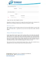
Page 24: ...m Figure 25 Example of Array Tag read from an Allen Bradley PLC If the Array Tag to be read is a bool array then the count represents the number of 32 Boolean blocks to read On Figure 26 an example is...

Page 25: ...esponds to the IP Address of the Main NTP server In normal operation the Date and Time will be requested from this server and updated internally Backup NTP Server Address This is the IP Address of an...

Page 26: ...the following parameters Command Delay This is a minimum delay to introduce between consecutive Modbus Polls This time is entered in Milliseconds and helps dealing with Modbus devices that are not abl...

Page 27: ...IZI Technology Inc 3651 Pegasus Dr Ste 117 Bakersfield CA 93308 USA Tel 661 412 3494 email sales izitechnology com www izitechnology com Figure 28 Modbus RTU Master Configuration Screen...

Page 28: ...IZI Technology Inc 3651 Pegasus Dr Ste 117 Bakersfield CA 93308 USA Tel 661 412 3494 email sales izitechnology com www izitechnology com Figure 29 Configuring Modbus RTU Commands...

Page 29: ...alTime 1 then initialTime os time Your script action goes in here end In the Startup Script an initialTime Variable is declared This variable will contain the last time the action has been executed In...

Page 30: ...lue from the SPX5 database word address 100 will be read and the square root of the value will be set in word address 105 in floating point format The value in address 105 will be sent to an Allen Bra...

Page 31: ...In the screen properties the user is able to select the dimensions as well as the background color Figure 31 shows the HMI Editor screen Figure 31 HMI Screens Editor Window Once a new screen is create...

Page 32: ...h the text Label Example in the properties window it can be seen all the possible option that can be changed on the label Value Multistate Values and Level Bars have most of the same properties as the...

Page 33: ...swap code INT16 Direction in Word swap code UINT32 Direction in Word swap code INT32 Direction in Word swap code REAL32 Direction in Word swap code BIT Direction in Bits Table 2 Function allowed in t...

Page 34: ...ured text or image will be shown with the selected Foreground and Background colors Figure 34 Multistate configuration window The Level Bar component allows changing the width or height according to a...

Page 35: ...IZI Technology Inc 3651 Pegasus Dr Ste 117 Bakersfield CA 93308 USA Tel 661 412 3494 email sales izitechnology com www izitechnology com Appendix...

Reviews: