Technosoft 2021
28
iPOS360x HX-CAN Technical Reference
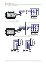
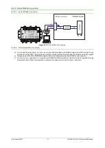
3.5.9.1
Supply Connection
Figure 3.5.9.1
Supply connection
CAUTION!
The logic power supply requires a minimum rising slew-rate of 75V/s in order to
correctly sample the operation mode and AxisID settings. The drive starts to
operate from 4.9V and samples correctly the AD circuit from 7V.
3.5.9.2
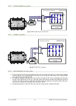
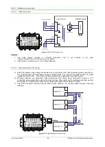
Recommendations for Supply Wiring
Always provide a nearby capacitor on the motor supply lines. The capacitor should be located within 10cm of the
iPOS360x edge connector, max. 20cm. The minimum recommended
capacitance is 330µF for iPOS3604, or 220µF for
iPOS3602, always rated at the appropriate voltage.
Use short, thick wires between the iPOS360x and the motor power supply. Connect power supply wires to all the
indicated pins. If the wires are longer than 2 meters, use twisted wires for the supply and ground return. For wires longer
than 20 meters, add a capacitor of at least 2,200μF (rated at an appropriate voltage) right on the terminals of the
iPOS3604, respectively 1,000μF for the iPOS3602
.
3.5.9.3
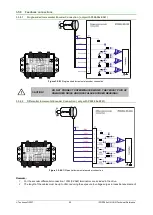
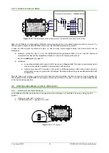
Recommendations to limit over-voltage during energy regeneration
During abrupt motion decelerations or reversals the regenerative energy is injected into the motor power supply. This
may cause an increase of the motor supply voltage (depending on the power supply characteristics). If the voltage gets
higher than 39V, the drive over-voltage protection is triggered and the drive power stage is disabled. In order to avoid
this situation you have 2 options:
Option 1. Add a capacitor on the motor supply
big enough to absorb the overall energy flowing back to the supply.
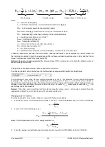
The capacitor must be rated to a voltage equal or bigger than the maximum expected over-voltage and can be sized
with the formula:
2
2
2
NOM
MAX
M
U
U
E
C
−
×
≥
where:
U
MAX
= 38V is the over-voltage protection limit
U
NOM
is the nominal motor supply voltage
E
M
= the overall energy flowing back to the supply in Joules. In case of a rotary motor and load, E
M
can be
computed with the formula:


