©
Technosoft 2022
17
iPOS4803 Microdrive EtherCAT Technical Reference
𝑍
𝐷𝐼𝐹𝐹
=
200
𝑠𝑞𝑟𝑡(𝐸
𝑟
)
(1 − 0.347𝑒 (−2.9
𝑆
𝐻
)) ln (
1.9(2𝐻 + 𝑇)
0.8𝑊 + 𝑇
)
Figure 11
Stripline Differential Impedance
For example:
{
𝑇 = 17.5 𝑚𝑖𝑐𝑟𝑜𝑛𝑠
𝐻 = 175 𝑚𝑖𝑐𝑟𝑜𝑛𝑠
𝐸
𝑟
= 4.8(𝐹𝑅4)
𝑊 = 4𝑚𝑖𝑙
𝑆 = 4 𝑚𝑖𝑙
→ 𝑍
𝐷𝐼𝐹𝐹
= 100.2 Ω
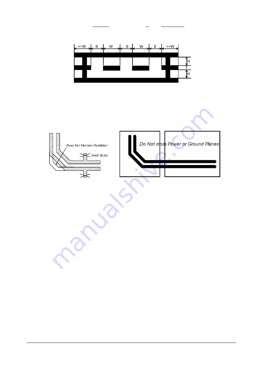
Figure 12
Stripline Differential Impedance
3.4.2.3.2
PCB EtherCAT routing indications
•
High-speed signals (Tx/Rx 0/1 +/-) must be routed as differential pairs, with controlled impedance, microstrip
or stripline.
•
Microstrip and stripline pairs shall be guarded on the same layer as the differential pair, with outer traces
connected to the return plane by vias. The guarding traces shall form preferably a closed ring, wherever
possible.
•
Use above formulae (or other method) to calculate microstrip or stripline differential impedance
•
Avoid stubs, crossovers and vias on high-speed signals. Vias present impedance discontinuities and should
be avoided. Route an entire differential pair trace on a single layer if possible.
•
High-speed signals should not be run such that they cross a plane split. A signal crossing a plane split may
cause unpredictable return path currents and would likely impact signal quality, also potentially creating EMI
problems.
•
The center tap of the magnetics isolated winding has a "Bob Smith" termination to chassis ground. "Bob
Smith" termination is used to reduce noise resulting from common-mode current flows, as well as reduce
susceptibility to any noise from unused wire pairs on the RJ45.
•
"Bob Smith" termination is different depending on Power Over Ethernet (PoE) compliance. PoE carries up to
57V between pairs, which would destroy the 75ohm terminating resistors if DC blocking capacitors of 10nF
are not in place.
•
Capacitor 1nF 2KV must sustain 1.5KVrms for 1 minute as per IEEE802.3. The 1Meg discharge resistor may
be destroyed during this hi-pot testing.
•
For enhanced EMC immunity it is possible to add surge protectors on the high-speed signals, on the isolated
side of the magnetics (not across pins, there is DC current flowing through windings). Check that signals are
not affected by the added parasitic capacitance.
•
Use magnetics with integrated common-mode choking devices. Use magnetics compatible with Auto
MDI/MDI-X (with symmetrical windings). Use metal shielded connectors, and connect the shield to device
chassis / PE.
•
Do not run any signals under the magnetics - this could cause unwanted noise crosstalk. Likewise void the
planes under magnetics, this will help prevent common-mode noise coupling.
•
To save board space and reduce component count, RJ45 connectors with integrated magnetics may be
used. Check the PoE compliance where applicable.


