Technosoft 2016
34
iPOS4808 MY-CAN-STO/-CAT-STO Technical Reference
2
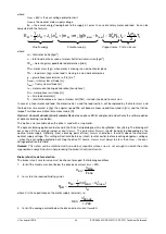
NOM
CYCLE
d
BR
BR
I
t
t
P
R
×
×
>
where t
CYCLE
is the time interval between 2 brakes in case of repetitive moves.
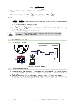
4. to be rated for an average power
CYCLE
d
BR
AV
t
t
P
P
×
=
and a peak power
BR
MAX
PEAK
R
U
P
2
=
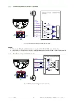
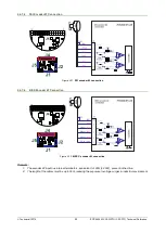
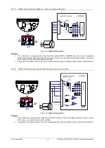
Remarks:
1. If
BR
BRAKE
PEAK
MAX
P
U
I
U
×
>
2
2
the braking power P
BR
must be reduced by increasing either t
d
– the time to decelerate
or C – the external capacitor on the motor supply
2. If
BR
BRAKE
NOM
CYCLE
d
BR
P
U
I
t
t
P
×
>
×
×
2
2
2
either
the braking power must be reduced (see Remark 1) or t
CYCLE
– the
time interval between braking cycles must be increased
WARNING!
THE BRAKE (SHUNT) RESISTOR MAY HAVE HOT SURFACES
DURING OPERATION.
3.6.9
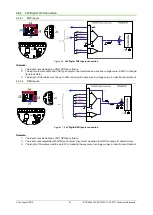
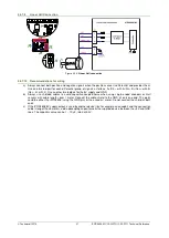
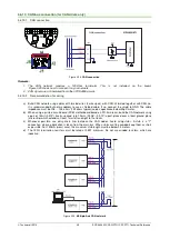
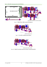
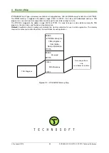
Serial RS-232 connection
3.6.9.1
Serial RS-232 connection
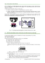
Figure 3.27.
Serial RS-232 connection
3.6.9.2
Recommendation for wiring
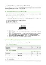
a) If you build the serial cable, you can use a 3-wire shielded cable with shield connected to BOTH ends. Do not
use the shield as GND. The ground wire (pin 31 of J4) must be included inside the shield, like the 232Rx and
232Tx signals
b) Always power-off all the iPOS4808 supplies before inserting/removing the RS-232 serial connector
c) Do not rely on an earthed PC to provide the iPOS4808 GND connection! The drive must be earthed through a
separate circuit. Most communication problems are caused by the lack of such connection

