


©
Technosoft 2007
33
PIM2401 Technical Reference
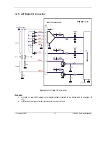
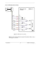
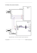
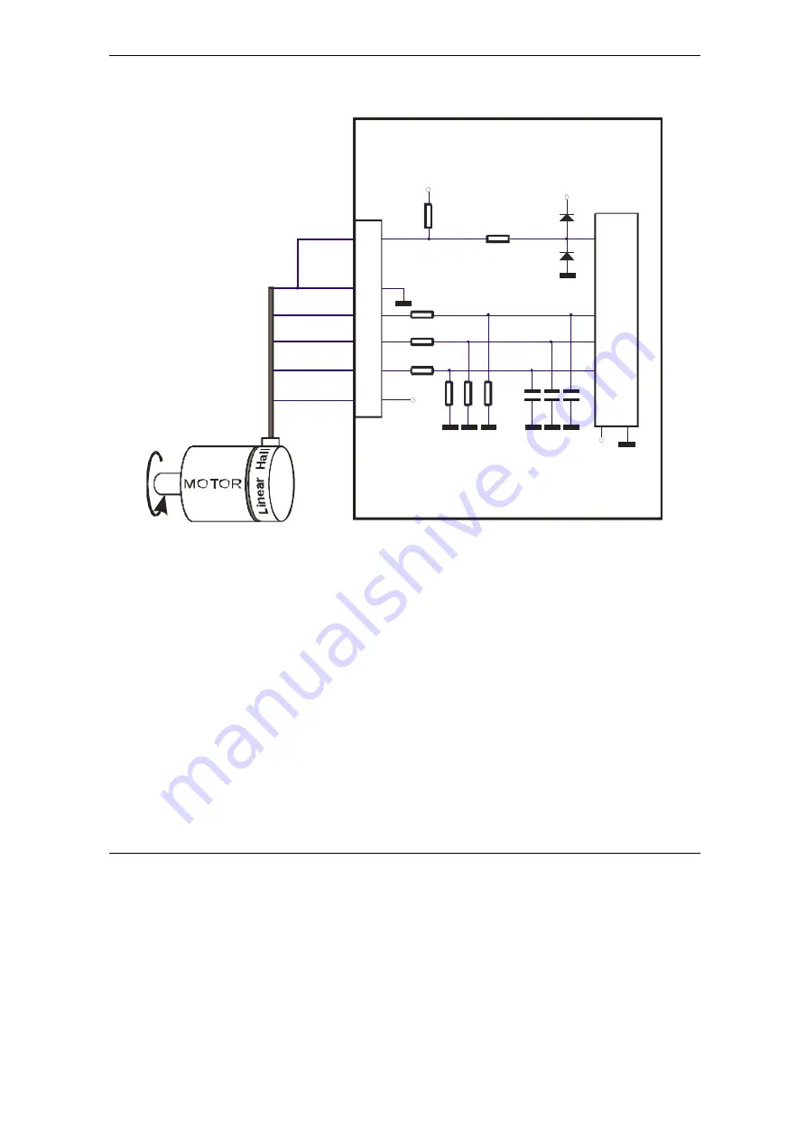
3.2.9.5
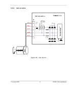
Linear Hall Auto-Setup connection
5
GND
+3.3V
B- / LH2
C- / LH3
14
Linear Hall Auto-Setup
connection
16
IBL2401 v1.0
Mo
ti
o
n
C
h
ip
TM
PIM2401 v1.0
+5V
+5V
OUT
J2
12
+5V
3 x 10K
3 x 20K
3 x 22nF
13
A- / LH1
6
+3.3V
1K
Hall1
1K
Figure 3.18.
Linear Hall Auto-Setup connection
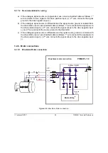
3.2.9.6
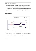
Recommendations for wiring
a) Always connect both positive and negative signals when the encoder or the Hall sensors
are differential and provides them. Use one twisted pair for each differential group of
signals as follows: Enc A+ with A-/LH1, Enc B+ with B-/LH2, Enc Z+ with Z-/LH3. Use
another twisted pair for the 5V supply and GND.
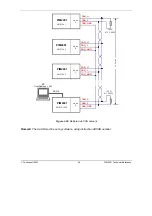
b) Always use shielded cables to avoid capacitive-coupled noise when using single-ended
encoders or Hall sensors with cable lengths over 1 meter. Connect the cable shield to the
GND, at only one end. This point could be either the PIM2401 (using the GND pin) or the
encoder / motor. Do not connect the shield at both ends.
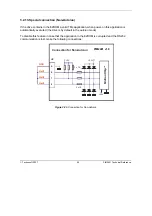
c) If the PIM2401 5V supply output is used by another device (like for example an encoder)
and the connection cable is longer than 5 meters, add a decoupling capacitor near the
supplied device, between the +5V and GND lines. The capacitor value can be 1...10
μ
F,
rated at 6.3V.
Summary of Contents for PIM2401
Page 2: ......
Page 4: ......
Page 8: ... Technosoft 2007 VI PIM2401 Technical Reference ...
Page 90: ... Technosoft 2007 80 PIM2401 Technical Reference This page is empty ...
Page 91: ......
Page 92: ......


