background image


17 

Filter Stalled 


Last Flush    

XFlsh


XXXX  min 
 

Loading Data 
From Memory 
 
 Techsys 
Corporation 
Version No. 0302 


POWER FAILURE 
About to restart 


INITIALISATION MESSAGES 
 

When the Filter Controller is first connected to power the following information messages are seen.  

 
Data stored in the Filter controller is the last stored data. Data is 
recalled after each power down. 


The software version number is displayed for 1 second on initial power up.  
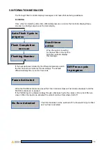
After Power Failure, data is saved to the memory and all changes are saved.  After a power failure the 
following message is displayed: 


6. ALARM MESSAGES 


The FILTER CONTROLLER has display messages to inform the operator of out of specification 
situations.  Messages are cleared by 

pressing the “ENTER” key after the fault has been cleared.  

 
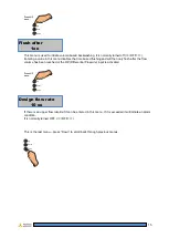
If the differential pressure switch remains closed for more than 15 
minutes it is assumed that the filter has 

Stalled/Blocked

. This 

message will remain active until the “

Enter

” button is pressed. The 

filter operation will continue after the fault is registered and until the 

fault is manually remedied on the filter. The fault alarm can be programmed to trip on this fault. 
 

FLUSH ALARM 

 
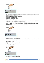
If the Total number of flushes in any one-hour period exceeds 
the “MAX. FLUSHES / Hr” setting then the Filter Controller will 
display this message. It is for informational purposes only to 
inform the operator that the system is being strained with either 
excess flow or excess contamination loading. 
 

TEST MODE 

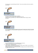
When the TEST Mode menu is selected for test flushing the 
screen will inform the operator that the filter is being flushed in 
this mode. 


TEST Mode ON 
Stop, Enter + Down 


Summary of Contents for FILTERFLUSH-001

Page 1: ...1 Scroll to Program Mode Adjust Step 2 Select ON by holding down Enter and pressing Up Step 3 Scroll through menu options by pressing Up or Down Step 4 Adjust settings by holding down Enter and press...

Page 2: ...t au More information is also supplied on our WEB site Internet contact www techsys net au This manual explains how to use the Techsys Filter Flush Controller There are other control systems available...

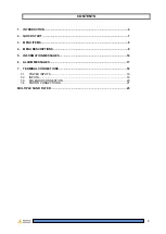
Page 3: ...UICK START 7 3 MENU ITEMS 8 4 MENU DESCRIPTIONS 9 5 INFORMATION MESSAGES 16 6 ALARM MESSAGES 17 7 TERMINAL CONNECTIONS 18 7 1 POWER INPUTS 19 7 2 INPUTS 19 7 3 SOLENOID CONNECTION 20 7 4 MOTOR CONNECT...

Page 4: ...enus that users can access to adjust settings to suit each application Menus and adjustments are made by pressing the UP or DOWN keys Up Enter Down Caution Dangerous Voltage Inside FILTER FLUSH CONTRO...

Page 5: ...nter Up To proceed further Program Mode has to be turned ON Press the Enter then the UP key Up Enter Down Program Mode Adjust Enter Up Program Mode will be turned to ON press the UP key Up Enter Down...

Page 6: ...rement Up Enter Down Backflush Time 31 Secs To decrease the Backflush Time setting press and hold the Enter key down and then press the DOWN key once for each second less Alternatively keep your finge...

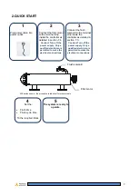
Page 7: ...Caution Turn off the power supply Only a qualified electrician is permitted to make the electrical connections 3 Connect the flush solenoid to the terminal strip inside the controller as detailed in s...

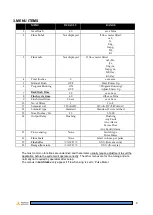
Page 8: ...il 12Volts DC 12Volts DC 24Volts AC 12 Solenoid type Standard Standard 2 wire latched 13 Max Flushes Hr 20 1 1000 14 Output Relay Flushing Flushing Any Fault Any Alarm Excess Flow Any Fault Alarm 15 F...

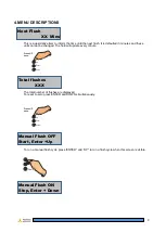
Page 9: ...very minute Press UP once Up Enter Down The total number of flushes are displayed To reset to zero press ENTER and DOWN simultaneously Press UP once Up Enter Down To run a manual flush cycle press ENT...

Page 10: ...ush Mode by displaying this message Press UP once Up Enter Down To access additional menus press the ENTER button and the UP button to change the Program Mode to ON Manual Flush ON Stop Enter Down Flu...

Page 11: ...ned as the time from when the last flush starts to the time when the next flush begins For continuous flushing select the cycle time to 0 This will continuously flush the filters To stop the controlle...

Page 12: ...re 24Volts AC or 12 Volts DC If operation is from an external 24VDC supply select the 12V DC option and ensure that 24VDC valve are used Press UP once Up Enter Down The FILTER CONTROLLER can activate...

Page 13: ...wn The FILTER CONTROLLER has one programmable output that can be set to any one of the following functions Program Function Description Delay time Flushing Any filter flushing 1 sec Any Fault Filter b...

Page 14: ...ot require flushing in a no flow condition NOTE If Switch Type is selected then the flow switch must have closed contacts for the system to flush Press UP once Up Enter Down If a pulse flow meter is f...

Page 15: ...lush after the flow volume has been reached or the DP Differential Pressure input is activated Press UP once Up Enter Down If there is an upper flow rate limit it can be entered in this menu If it is...

Page 16: ...nds When the PAUSE terminals are closed the Filter Controller stops will not initiate a backwash until the PAUSE contacts are re opened If the PAUSE input is activated midway through a backwash cycle...

Page 17: ...pressing the ENTER key after the fault has been cleared If the differential pressure switch remains closed for more than 15 minutes it is assumed that the filter has Stalled Blocked This message will...

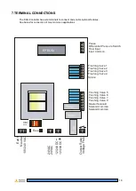
Page 18: ...lay Relay Pause Differential Pressure Switch Flow Input Input Common Flushing Valve 1 Flushing Valve 2 Flushing Valve 3 Flushing Valve 4 Spare Flushing Valve 5 Flushing Valve 6 Flushing Valve 7 Flushi...

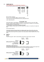
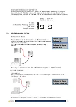
Page 19: ...ed All power supplies connected with 12 24 VDC require an in line fuse of no more than 2 5 amps to be fitted 24VAC POWER SUPPLY Connection to the 24V AC power supply is not polarity sensitive Any of t...

Page 20: ...ENOID CONNECTION STANDARD SOLENOID The standard solenoid should be connected to the terminal strip as shown As more filters are required connect the flushing valve solenoids to the terminals sequentia...

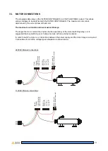
Page 21: ...various voltages to be switched with the FILTER CONTROLLER The maximum motor size is determined by the current draw of that motor The maximum current should never exceed 8 amps The larger the motor c...

Page 22: ...ies or when the motor current exceed 5 amps it is a requirement to use a contactor to switch the mains power to the motor Simply supply the control voltage to the motor switch relay and then connect t...

Page 23: ...w Input Input Common Flushing Valve 1 Spare Flushing Valve 2 Flushing Valve 3 Flushing Valve 4 Flushing Valve 5 Flushing Valve 6 Flushing Valve 7 Flushing Valve 8 Master Solenoid Solenoid common Solen...

Page 24: ...VDC 12 24VDC Output Relay Voltage Free 230V Fuse Pause Differential Pressure Switch Flow Input Input Common Flushing Valve 1 Spare Flushing Valve 2 Flushing Valve 3 Flushing Valve 4 Flushing Valve 5 F...

Page 25: ...ing 8 flow switch 14 20 flush 16 flush alarm 17 flushes 13 17 flushing time 11 initialisation messages 17 Input 13 19 inputs 18 Internet 2 last flush 9 Max Flushes Hr 8 max motor size 21 maximum flush...

Reviews: