19
7.1.
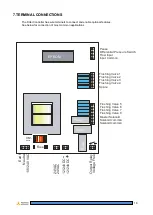
POWER INPUTS
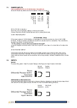
Use a qualified Electrician to make power connections.
Power terminals are labeled and on the bottom of the circuit board.
E
a
rt
h
N
e
u
tr
a
l
1
1
0
V
A
C
a
c
ti
v
e
2
4
0
V
A
C
a
c
ti
v
e
2
4
V
A
C
-
2
4
V
A
C
+
1
2
V
D
C
-
1
2
V
D
C
+
M
o
to
r
p
o
w
e
r
in
M
o
to
r
s
w
it
c
h
e
d
o
u
tp
u
t
240 or 110VAC connection:
Select the correct operating voltage on the selector switch.
Connect the Active, Earth and Neutral wires to the relevant terminals.
12VDC POWER SUPPLY
FIT EXTERNAL FUSE
If the power supply is 12VDC (battery or solar power) connect the power via a fuse to the 12VDC
terminals. These are polarity sensitive and need to be checked prior to connection. The unit will also
operate from 24VDC on these terminals.
**
If the polarity is incorrect the board will be damaged**
All power supplies connected with 12-24 VDC require an in line fuse of no more than 2.5 amps to be
fitted.
24VAC POWER SUPPLY
Connection to the 24V AC-power supply is not polarity sensitive. Any of the 24 VAC wires can be
connected to the 24VAC terminals. If a motor is used with this option it will need to be wired to the
motor switch terminal. See Motor Connections. Be sure to provide a FUSED POWER SUPPLY for this
option.
7.2.
INPUTS
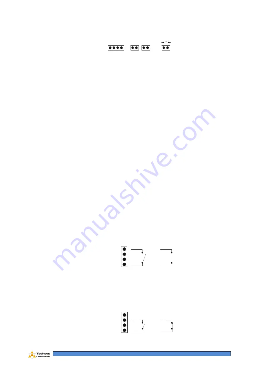
PAUSE
To pause the system, close the contact between the Pause and Input common terminals
Pause
Differential Pressure Switch
Flow Input
Input Common
Normal
Operation
System
Paused
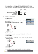
DIFFERENTIAL PRESSURE (PD)
A closed contact will activate a flush cycle. Closure of these contacts will override the time based flush
command. Once the system flushes, the timer for the time based flushing will reset.
Pause
Differential Pressure Switch
Flow Input
Input Common
Normal
Operation
Start flush
cycle


