TD20 Series VFD
Installation Guide
-13-
Terminal
Terminal name
Function
PE
Grounding terminal
Each machine should be grounded.
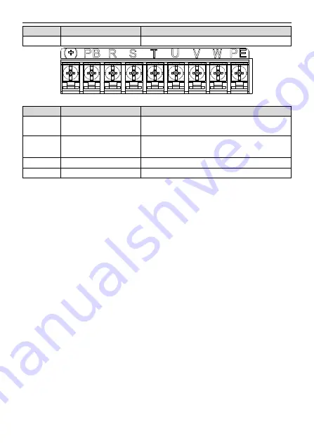
Figure 3-5 3PH terminals of main circuit
Terminal
Terminal name
Function
R, S, T
Power input of the main circuit
3-phase AC input terminals which are generally
connected with the power supply.
U, V, W
The VFD output
3-phase AC output terminals which are generally
connected with the motor.
PB, (+)
Braking resistor terminal
PB and (+) are connected to the external resistor.
PE
Grounding terminal
Each machine should be grounded.
Note:
•
Do not use asymmetrically motor cables. If there is a symmetrically grounding conductor in the motor
cable in addition to the conductive shield, connect the grounding conductor to the grounding terminal
at the VFD and motor ends.
•
Route the motor cable, input power cable and control cables separately.
•
When selecting C3 input filters, connect the filters in parallel at the input side of the VFD.
3.2.3 Wiring of terminals in main circuit
1.
Connect the ground line of input power cable to the ground terminal of VFD (PE) directly, and
connect 3PH input cable to R, S and T and fasten up.
2.
Connect the ground line of motor cable to the ground terminal of the VFD, and connect the 3PH
motor cable to U, V, W and fasten up.
3.
Connect the brake resistor which carries cables to the designated position.
4.
Fasten up all the cables on the outside of the VFD if allowed.
Summary of Contents for TD20 Series
Page 1: ......
Page 129: ...TD20 Series VFD Appendix C Peripheral Options and Parts 127 PB External brake resistor TD20...
Page 131: ......


