TD20 Series VFD
Communication Protocol
-95-
7 Communication Protocol
7.1 Brief instruction to Modbus protocol
Modbus protocol is a software protocol and common language which is applied in the electrical controller.
With this protocol, the controller can communicate with other devices via network (the channel of signal
transmission or the physical layer, such as RS485). And with this industrial standard, the controlling
devices of different manufacturers can be connected to an industrial network for the convenient of being
monitored.
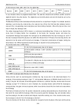
There are two transmission modes for Modbus protocol: ASCII mode and RTU (Remote Terminal Units)
mode. On one Modbus network, all devices should select same transmission mode and their basic
parameters, such as baud rate, digital bit, check bit, and stopping bit should have no difference.
Modbus network is a controlling network with single-master and multiple slaves, which means that there
is only one device performs as the master and the others are the slaves on one Modbus network. The
master means the device which has active talking right to sent message to Modbus network for the
controlling and inquiring to other devices. The slave means the passive device which sends data
message to the Modbus network only after receiving the controlling or inquiring message (command)
from the master (response). After the master sends message, there is a period of time left for the
controlled or inquired slaves to response, which ensure there is only one slave sends message to the
master at a time for the avoidance of singles impact.
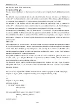
Generally, the user can set PC, PLC, IPC and HMI as the masters to realize central control. Setting
certain device as the master is a promise other than setting by a bottom or a switch or the device has a
special message format. For example, when the upper monitor is running, if the operator clicks sending
command bottom, the upper monitor can send command message actively even it can not receive the
message from other devices. In this case, the upper monitor is the master. And if the designer makes the
VFD send the data only after receiving the command, then the VFD is the slave.
The master can communicate with any single slave or with all slaves. For the single-visiting command,
the slave should feedback a response message; for the broadcasting message from the master, the
slave does not need to feedback the response message.
7.2 Application of the VFD
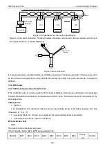
The Modbus protocol of the VFD is RTU mode and the physical layer is 2-wire RS485.
7.2.1 2-wire RS485
The interface of 2-wire RS485 works on semiduplex and its data signal applies differential transmission
which is called balance transmission, too. It uses twisted pairs, one of which is defined as A (+) and the
other is defined as B (-). Generally, if the positive electrical level between sending drive A and B is
among +2
–+6V, it is logic "1", if the electrical level is among -2V–-6V; it is logic"0".
485+ on the terminal board corresponds to A and 485- to B.
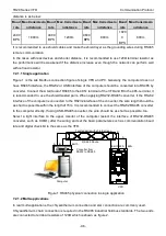
Communication baud rate means the binary bit number in one second. The unit is bit/s (bps). The higher
the baud rate is, the quicker the transmission speed is and the weaker the anti-interference is. If the
twisted pairs of 0.56mm (24AWG) is applied as the communication cables, the Max. Transmission
Summary of Contents for TD20 Series
Page 1: ......
Page 129: ...TD20 Series VFD Appendix C Peripheral Options and Parts 127 PB External brake resistor TD20...
Page 131: ......


