background image


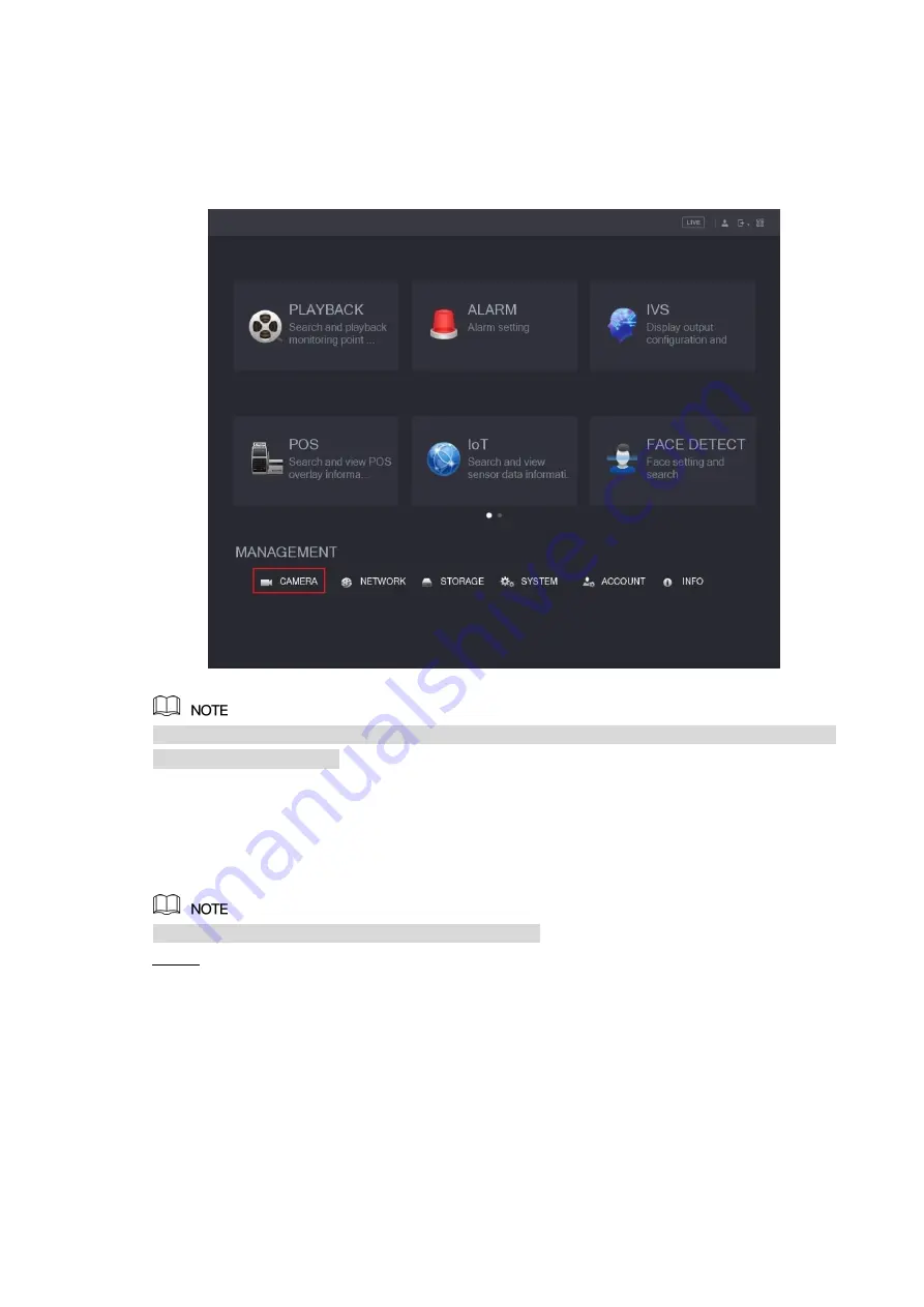
Figure 4-2

Right-click anywhere on the screen to return to the previous menu until you goes back to the 

live view screen interface. 

4.2 

Setting Audio Input 

Audio signal acquisition is available on select models. 

  In the 

Main Menu

 interface (Figure 4-2), select 

CAMERA > ENCODE > Encode

Step 1

The Encode setting interface is displayed. See Figure 4-3. 

Summary of Contents for HBE5P4WZ-S/A

Page 1: ...HBE5P4WZ S A 5MP 4 in 1 Motorized Bullet Camera ...

Page 2: ...10 Privacy Protection Notice As the device user or data controller you might collect personal data of others such as face fingerprints car plate number Email address phone number GPS and so on You need to be in compliance with the local privacy protection laws and regulations to protect the legitimate rights and interests of other people by implementing measures include but not limited to providin...

Page 3: ...ny problem occurred when using the device If there is any uncertainty or controversy please refer to our final explanation Important Safeguards and Warnings Electrical Safety All installation and operation should conform to your local electrical safety codes The power source shall conform to the requirement of the Safety Extra Low Voltage SELV standard and supply power with rated voltage which con...

Page 4: ... RG59 coaxial cable or higher standard Use standard components or accessories provided by manufacturer and make sure the device is installed and maintained by professional engineers The surface of the image sensor should not be exposed to laser beam radiation in an environment where a laser beam device is used Do not provide two or more power supply sources for the device otherwise it might damage...

Page 5: ...tions like financial center telecom site supermarket hotel government school and factory 1 2 Features 720p series support over 800 meter real time transmission of video and control signal from RG59 cable for 1080p to 4k series the distance is 500 meter Excellent low light performance with IR or night vision technology Configuring devices easily with OSD menu Support switching between HD SD outputs...

Page 6: ...2 2 Cable Figure 2 5 Figure 2 6 Figure 2 7 Figure 2 8 Figure 2 9 Figure 2 10 ...

Page 7: ...se be sure to supply power as instructed in the manual Device abnormity or damage could occur if power is not supplied correctly Video Output Connects to XVR to output video signal Audio Input Connects to sound pick up devices to receive analog audio signal Power Output Supplies DC12V 2W power DIP Switch Dial switches to change output mode Switch up indicates ON switch down indicates OFF Table 2 1...

Page 8: ...erent approaches required according to different mounting surfaces For masonry mounting surface insert expansion bolts from the accessory pack in the screw holes For wooden mounting surface expansion bolts are optional Step 3 Adjust the location of the bracket according to cable outlet requirement top out or side out and then pull the cable out through mounting surface or the side cable tray Step ...

Page 9: ...following instructions will guide you to configure your camera The number of the coaxial port on XVR will display at the lower left corner of the live view window to indicate the corresponding camera 4 1 Opening Main Menu Step 1 In the live view screen interface right click anywhere on the screen The shortcut menu is displayed See Figure 4 1 Figure 4 1 Step 2 Click Main Menu The Main Menu interfac...

Page 10: ...us menu until you goes back to the live view screen interface 4 2 Setting Audio Input Audio signal acquisition is available on select models In the Main Menu interface Figure 4 2 select CAMERA ENCODE Encode Step 1 The Encode setting interface is displayed See Figure 4 3 ...

Page 11: ...tting interface is displayed See Figure 4 4 Figure 4 4 In the More Setting interface you can configure the audio settings Step 4 Enable Audio Encode function In the Audio Format list leave to the default In the Audio Source list select HDCVI Click Save to save the settings Step 5 The Encode setting interface is displayed In the Encode setting interface Figure 4 3 click Apply Step 6 ...

Page 12: ...e is displayed See Figure 4 5 Figure 4 5 Click to see more options See Figure 4 6 Step 3 Figure 4 6 Click Step 4 The MENU OPERATION panel is displayed See Figure 4 7 The OSD menu of the corresponding camera is displayed on the live view screen Figure 4 7 For the function of the buttons in the MENU OPERATION panel see Table 4 1 Button Function Button Function Enter or confirm an item Select item Ex...

Page 13: ...t after sale service for desiccant replacement if there is condensed fog found on the lens after unpacking or when the desiccant turns green Not all models are included with the desiccant Maintaining Lens and Mirror Surface The lens and mirror surface are covered with antireflection coating which could be contaminated or damaged and result in lens scratches or haze image when being touched with du...

Reviews: