background image

www.tecnaonline.com  -  info@tecnaonline.com

E N G L I S H

14

ANNEX

PAR

DESCRIZIONE

14.2

PROOF OF MAINTENANCE

Copy if necessary

Date

Operating 

hours

Work carried out 

Carried out by name, 

signature

OPERATING MANUAL

 - 

H

ydraulic


breakers

 T 

series

44

/44

REV


0.0

ANNEX

14

Summary of Contents for T aD168

Page 1: ...OPERATING MANUAL Hydraulic breakers T series ENGLISH ...

Page 2: ...ing process All rights reserved by TECNA Group Srl including the industrial property rights Every power of disposal such as the right to copy and transfer is reserved A sample configuration is shown on the front page The product delivered can thus deviate from the figure OPERATING MANUAL Hydraulic breakers T series TECNA Group Srl Zona Industriale Via Abruzzo 86 70021 Acquaviva delle Fonti BA ITAL...

Page 3: ... AND REMOVING THE PLUG TOOL 20 6 7 CONNECTING THE HYDRAULIC BREAKER HYDRAULICALLY 22 7 COMMISSIONING 25 7 1 FIRST COMMISSIONING RE COMMISSIONING AFTER A STANDSTILL 25 8 OPERATION 26 8 1 OPERATING RANGE 26 8 2 SITE SELECTION 26 8 3 INFORMATION REGARDING THE MODE OF OPERATION 27 8 4 PROCESS FLOW 31 8 5 UNDERWATER OPERATION 31 9 TOOL 32 9 1 TOOL 32 10 MAINTENANCE DIN EN 31051 33 10 1 CLEANING AND SER...

Page 4: ...ion for a long time if the instructions are observed carefully Applicable documents Spare parts catalogue including the parts list and drawings Technical details regarding the hydraulic breakers Applicable documents regarding supplied components see section 14 ANNEX on page 43 See the parts list for the operating manual and data sheets of the individual components Detailed information regarding th...

Page 5: ...at parts and special equipment that has not been delivered by us has also not been approved by us Installing and or using such products can affect the safety 4 44 REV 0 0 GENERAL INFORMATION 1 1 GENERAL INFORMATION PAR DESCRIPTION 1 3 FOR BETTER UNDERSTANDING OF THIS MANUAL CONVENTIONS DANGER This danger sign indicates an imminent great danger that in all probability causes severe injuries or even...

Page 6: ...ible for all the damage caused due to improper use The hydraulic breaker is not suitable for operation in an explosive environment and the parameters and information in the mounting instruction are applicable at sea level The following is included under intended use Following all the notes from the mounting instruction Following the requirements prohibitions and warnings and Adhering to the inspec...

Page 7: ...A DANGER AREA WARNING ABOUT A HOT SURFACE USE EAR MUFFS DISPOSE OF THE WASTE OIL IN ACCORDANCE WITH THE STATUTORY REQUIREMENTS More prohibition warning mandatory and instruction signs of components may be affixed on the support frame and on attachments of the support frame Information regarding the individual prohibition warning mandatory and instruction signs can be found in the relevant operatin...

Page 8: ...ring caps or seals You may not fundamentally modify or re construct the hydraulic breaker Use the hydraulic breaker within the range of capacity only which is specified in the Technical Details Do not use the hydraulic breaker in explosive environments if there is no explicit permission for it Close the front panel of the support frame before you start working with the hydraulic breaker Wear the n...

Page 9: ...ing operation If they are damaged measures must be taken immediately such that there is no danger due to it Do not work with the hydraulic breaker if any persons are present on the hydraulic breaker Depending on the type of connection keep in mind the pressure condition when connecting to the hydraulic system and when separating from the hydraulic system The hydraulic system must be operated at ze...

Page 10: ...aker and support frame FOR COMMISSIONING Ensure that all the hydraulic connections are covered or closed Operate a fully installed hydraulic breaker only FOR CLEANING Close all the openings using suitable protective equipment such that the cleaning agents do not enter the system Use a suitable cleaning device for cleaning and follow the instructions regarding the cleaning device Wear protective cl...

Page 11: ...as well as the legal regulations Intended operation of the hydraulic breaker Following the instructions of the site management and the operating instructions of the site operator Behaviour in case of an emergency 2 SAFETY PAR DESCRIPTION 2 6 PERSONAL PROTECTIVE EQUIPMENT The instructions from the regulations rules national laws and ordinances must be adhered to Follow the country specific rules an...

Page 12: ...the scope of delivery Hydraulic hammer according to technical specification and order specification Check the scope of delivery for completeness Check the scope of delivery for possible transportation damage also see section 5 TRANSPORT AND STORAGE on page 14 Check whether the operating manual is suitable for the hydraulic breaker OPERATING MANUAL Hydraulic breakers T series ...

Page 13: ... A sample design has been shown in the following figure The delivered hydraulic breaker can thus deviate from the figure Inform your dealer or TECNA if the Technical Details are not provided during the delivery 1 Support for the quick change device 2 Locking pins 3 Tool 4 Retaining wedges 5 Hydraulic connection OUT 6 Hydraulic connection IN OPERATING MANUAL Hydraulic breakers T series 12 44 REV 0 ...

Page 14: ... Manufacturer logo TECNA Italian Excellence 2 Name and address of the manufacturer TECNA Group Srl Via Principe Amedeo 146 74121 Taranto TA I 3 CE mark CE 4 Model name z B HF40 5 Serial number z B 1234 6 Input power max z B KW 22 7 Breaker working pressure z B bar 120 8 Date of manufacture year and week z B 2009 FIGURE 2 Identification plate TABLE 1 Information regarding the identification plate T...

Page 15: ...able technique for lifting putting down and moving Use personal protective equipment e g gloves work shoes protective goggles work clothing etc Do not transport the hydraulic breakers on parts which have low stability e g connecting hoses DANGER OF DAMAGE TO HEALTH There is a danger of damage to health when lifting the hydraulic breaker or tool Use a suitable technique for lifting putting down and...

Page 16: ...arts which have low stability e g connecting hoses Ensure that the sling gear does not rest on parts which have low stability Take into consideration the following points during transportation Properties of the load e g weight centre of gravity fastening and suspension points Manner of suspending or lifting the load Ensure that the load bearing capacity of the lifting tool is sufficient for transp...

Page 17: ...s long as the following criteria are met The hydraulic breaker should be stored in the downward direction perpendicular to the tool so that the existing seals are not damaged due to the dead weight of the hydraulic breaker DANGER OF MATERIAL DAMAGE AND PERSONAL INJURIES The hydraulic breaker must be secured as per the regulations for perpendicular storage to prevent it from falling down so that th...

Page 18: ...r mounting The quick changer must be attached properly to the support frame and must be functional 6 MOUNTING THE HYDRAULIC BREAKER PAR DESCRIPTION 6 3 REQUIRED TOOL You can mount and remove the hydraulic breaker using commercial tools 6 MOUNTING THE HYDRAULIC BREAKER PAR DESCRIPTION 6 4 NECESSARY ACCESSORIES You need the following accessories for mounting the hydraulic breaker on the support fram...

Page 19: ...lic breaker and or the support frame Check whether you are using the correct hydraulic breaker on the basis of the model name on the identification plate Check the scope of delivery for completeness Check the scope of delivery for possible damage due to transportation Check whether the operating manual is suitable for the hydraulic breaker 1 You must ensure that the surroundings are clean before m...

Page 20: ... H 4 Secure the hydraulic breaker on the quick changer PAR DESCRIPTION 6 5 MOUNTING FIGURE 4 Holding the hydraulic breaker FIGURE 5 Securing the hydraulic breaker OPERATING MANUAL Hydraulic breakers T series 19 44 REV 0 0 MOUNTING THE HYDRAULIC BREAKER 6 ...

Page 21: ... the plug tool FIGURE 7 Pushing in the plug tool 1 Press the locking pin 1 in 2 Remove the retaining wedge 3 3 Press the locking pin 2 in 4 Remove the retaining wedge 4 5 Push in the plug tool 5 and pay attention to the correct position of the fastening through the retaining wedges 3 and 4 OPERATING MANUAL Hydraulic breakers T series 20 44 REV 0 0 MOUNTING THE HYDRAULIC BREAKER 6 ...

Page 22: ...Transport the plug tool securely and use a lifting gear if necessary 6 Storing the plug tool safely and securing it against shifting FIGURE 8 Removing the plug tool REMOVING THE PLUG TOOL CAUTION Pay attention to the weight of the plug tool Transport the plug tool securely and use a lifting gear if necessary 6 Insert the retaining wedges 3 and 4 again till the locking pins 1 and 2 are released aga...

Page 23: ...nt cloth for cleaning Do not use hemp as a sealant DANGER OF INJURY WHEN MOUNTING UNDER PRESSURE Ensure that the hydraulic lines and hoses are at zero pressure before your start connecting otherwise you can get injured or damage the hydraulic breaker or the hydraulic system Connect the relevant part of the hydraulic system at zero pressure before you fit the connecting hoses Follow the instruction...

Page 24: ...al mechanical forces during operation which reduces the service life of the hydraulic breaker and the support frame hydraulic system Fit the lines and hoses without tensioning 3 Connect all the connections and follow the support frame operating manual Pay attention to the different designs of the hydraulic connections of the hydraulic breaker in the following figures CAUTION OPERATING MANUAL Hydra...

Page 25: ...lic hoses to the support frame and follow the operating manual of the support frame 7 Ensure that hoses are connected to all the connections or that the connections are closed using lock screws 8 Ensure by checking that the pipe fittings are tightened correctly 9 Ensure that the pipes and hose lines and every combination of fittings couplings or joints with hoses or pipes are checked for their saf...

Page 26: ...aulic breaker HEATING THE HYDRAULIC BREAKER Work carefully if the temperature of the hydraulic breaker is below 20 C so that the hydraulic breaker can heat up slowly Ensure that the temperature range of the pressure medium is optimum on the support frame see operating manual of the support frame CONDUCT A LEAKAGE TEST Conduct a functional check of the hydraulic breaker by working briefly with the ...

Page 27: ...E DANGER OF MATERIAL DAMAGE AND PERSONAL INJURIES The support frame may be come unstable if used beyond the prescribed operating range where it would no longer have any stability and can topple Nobody should be present within 10 m of the tool when the hydraulic breaker is in operation since torn material can fly around Stick to the operating range and follow the operating manual of the support fra...

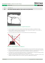
Page 28: ... correct tool and method for the corresponding material when working see chapter 9 TOOL on page 32 Use a moil point or chisel tool for breaking the material by penetrating into it FIGURE 12 Breaking the material by penetrating FIGURE 13 Breaking the material using a mechanical pressure wave Use a blunt tool for breaking the material using pressure wave OPERATING MANUAL Hydraulic breakers T series ...

Page 29: ...egularities on the surface to be broken when positioning the tool Put correct pressure with the jib Vibrations can be transferred to the support frame which can cause damage to the support frame in case of too low or too high pressure of the jib on the hydraulic breaker Avoid strokes without load since it may damage the hydraulic breaker Do not use the hydraulic breaker as a ripper or break lever ...

Page 30: ...able point where the tool can penetrate e g a weak spot in the material Do not rotate the support frame such that you take support of the tip Keep the hydraulic breaker in a perpendicular position for at least one minute after every working hour if the hydraulic breaker has been operated in a horizontal position or upside down position This allows stones to come out from the bush for instance FIGU...

Page 31: ...ange Work very carefully for the first 15 minutes at temperatures below 0 C so that the tool can heat up slowly The tool should not be heated more than necessary e g with a welding torch According to the Technical Details of the dealer or authorised Service change the nitrogen filling pressure if the hydraulic oil temperature is constantly above 70 C Always keep the hydraulic breaker vertical if i...

Page 32: ... hydraulic breaker The correct pressure is built if the support frame gives the impression of becoming lighter Start the hydraulic breaker and follow the instructions in section 8 3 INFORMATION REGARDING THE MODE OF OPERATION on page 27 Maintain the pressure and break the material by penetrating or by means of pressure waves Change the position of the hydraulic breaker if the material is not broke...

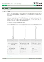
Page 33: ...an also influence this choice The following overview serves as general information TABLE 2 Tool Chisel tool Moil point tool Blunt tool Method Penetrate and break Method Penetrate and break Method Knock and break Suitable for all kinds of digging or narrow trenching on soft medium stratified rocks Suitable for fine medium concrete demolition or soft non stratified rocks Secondary breaking of hard a...

Page 34: ...a suitable cleaning device and follow the instructions regarding the cleaning device DAMAGE TO THE HYDRAULIC SYSTEM AND SEALS The water pressure of a cleaning device can damage the hydraulic system and seals of the hydraulic breaker Water displaces the oil from the hydraulic system and the seals Use a suitable cleaning device and follow the instructions regarding the cleaning device Close all the ...

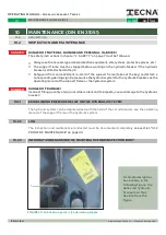
Page 35: ... Incorrect filling quantity and or unsuitable lubricant tool paste causes damage to the hydraulic breaker The hydraulic system can be depressurised with the help of the circuit diagram see the operating manual of the support frame or the hydraulic system The inspection and maintenance conducted must be documented completely see section 14 2 PROOF OF MAINTENANCE on page 44 10 MAINTENANCE DIN EN 310...

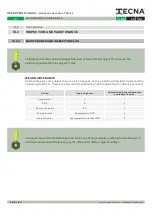
Page 36: ...e and inspection plan Semi diurnal 4 1 Daily 8 2 Once in two weeks 80 3 Every 6 months Approximately 1000 4 Every 12 months Approximately more than 1500 5 10 2 4 MAINTENANCE AND INSPECTION PLAN You must reduce the maintenance interval in case of major stress on the hydraulic breaker or due to environmental influences e g lot off dust formation high humidity Follow the maintenance and inspection in...

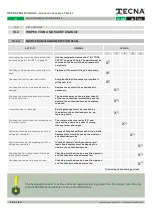
Page 37: ... dealer or an authorised service e g replacing seals X1 Checking the tool and the tool holder bush for traces of wear The tool must be rotated by 180 and replaced by a new one in case of strong traces of wear and ridges X1 Replacing the seals and diaphragms of the nitrogen accumulator In case of tough conditions and strong loads Replacement must be done by the dealer or an authorised service X1 Re...

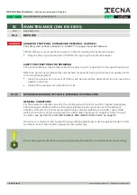
Page 38: ...not use cotton waste for cleaning Close all the openings using protective caps DANGER 37 44 REV 0 0 MAINTENANCE DIN EN 31051 10 10 3 5 NITROGEN CHARGING OF THE OIL NITROGEN ACCUMULATOR GENERAL CONDITIONS For the breaker to operate correctly the oil nitrogen accumulator must be charged adequately The discharged condition of the accumulator is shown by strong vibrations of the hydraulic breaker s oi...

Page 39: ...tallation requirements have not been met see DIN 20066 The duration of storage and use has been exceeded 10 MAINTENANCE DIN EN 31051 PAR DESCRIPTION 10 4 SPARE AND WEAR PARTS DAMAGE TO PROPERTY AND PERSONS DUE TO DEFECTIVE SPARE PARTS Spare parts which do not meet the technical requirements specified by TECNA can cause damage to persons and property Use the original spare parts provided by TECNA S...

Page 40: ...ion for removal 2 Connect the connections to the hydraulic breaker at zero pressure see the operating manual of the support device 3 Provide a container for collecting the emergent hydraulic fluid 4 Fit the hydraulic hoses between the jib and hydraulic breaker 5 Collect the emergent hydraulic fluid in the container provided and dispose it legally 6 Close the connections using the corresponding pro...

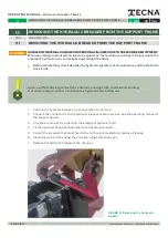
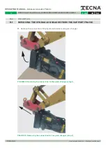
Page 41: ...UPPORT FRAME 8 Remove the connection of the hydraulic breaker and quick changer FIGURE 22 Removing the connection to the quick changer step 1 FIGURE 23 Removing the connection to the quick changer step 2 OPERATING MANUAL Hydraulic breakers T series 40 44 REV 0 0 REMOVING THE HYDRAULIC BREAKER FROM THE SUPPORT FRAME 11 ...

Page 42: ...medium as per the country specific regulations The hydraulic breaker does not emit any hazardous substances if it is used as directed Hence there are no negative effects on human beings and the environment under normal circumstances The hydraulic breaker can be reused mainly with respect to the material because of the high metal content An optimum metal recycling can be achieved by dismantling ind...

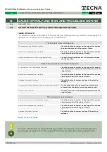
Page 43: ...manual of the support frame Hydraulic oil temperature is too high Check the hydraulic system on the support frame see operating manual of the support frame Leakage in hydraulic system Check the hydraulic system and repair the existing leakages Accumulator defect pressure hoses are vibrating strongly Get the diaphragm of the accumulator removed or replaced from the dealer or an authorised service O...

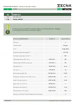
Page 44: ...operating range dry film C 1150 Worked penetration 20 C dmm ASTM D 217 250 Worked stability 100 000 strokes dmm ASTM D 217 275 Dropping point C ASTM D 566 none Pour point C ASTM D 97 24 Base oil viscosity grade ISO ASTM D 445 1000 4 ball wear test 1200 rpm 75 C 40 Kg 1 h mm ASTM D 2266 0 7 4 ball EP Test weld load Kg ASTM D 2783 800 Evaporation 22 h 150 C ASTM D 972 1 Resistance in humid cabin h A...

Page 45: ...aonline com E N G L I S H 14 ANNEX PAR DESCRIZIONE 14 2 PROOF OF MAINTENANCE Copy if necessary Date Operating hours Work carried out Carried out by name signature OPERATING MANUAL Hydraulic breakers T series 44 44 REV 0 0 ANNEX 14 ...

Page 46: ...ency it TECNAGroup Srl Zona Industriale Via Abruzzo 86 70021 Acquaviva delle Fonti BA ITALY Headquarters Via Principe Amedeo 146 74121 Taranto TA ITALY phone 39 0 80 7810000 39 0 80 3050136 fax 39 0 80 3051812 info tecnaonline com tecnagroup pec it www tecnaonline com ...

Reviews: