background image


P92 Classic Jabiru


M a i n t e n a n c e   M a n u a l


SYSTEMS 


Page E-12 

Date

Issue 3: 4

th

 July 2011          


Section E 


8 - EMERGENCY PARACHUTE SYSTEM 

(optional)


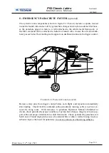
The  system's  main  components  (shown  in  figure  E-12  below)  include  a  capsule  located 
inside the launch tube and set-off by pyrotechnic charges and a nylon container that hous-
es  the  parachute  rigged,  in  turn,  to  a  cable  attached  to  the  cabin's  metal  framework.    A 
flexible command cable is attached to bottom of launch tube, crosses the aft cabin bulk-
head, passes below floor matting and reappears on dashboard connected to trigger control. 


F

IGURE 

E-11


P

ARACHUTE INSTALLATION


Remove  safety  pins  from  trigger  control  before  each  flight    and  reposition  immediately 
after landing.  Check flexible command cable periodically insuring cable is not bent ex-
cessively  along  route.    With  reference  to  parachute  Operator's  Manual  (furnished  to 
client), check periodically proper condition of pyrotechnic charges, integrity of main sup-
port cable and proper attachment to cabin framework.  Check periodically parachute exit 
hatch and, if found unglued (because of accidental hits or other ) reattach using two-face 
adhesive tape as that used for upholstery; do not use silicone or other strong adhesive. 


Summary of Contents for P92 Echo Classic Jabiru

Page 1: ...Maintenance Manual 3nd Issue July 04th 2011 Revision 0 ...

Page 2: ...endably for a long time with optimal performance in absolute safety This manual consists of 5 sections a table of contents at the beginning of each section will allow you to reach quickly any selection Information contained herein is based on available data at time of publication possible variations shall be presented in servicing bulletins This manual describes correct servicing of parts manufact...

Page 3: ...C C 1 4th July 2011 ii C 2 iii C 3 iv C 4 C 5 C 6 C 7 A A 1 4th July 2011 C 8 A 2 C 9 A 3 C 10 A 4 C 11 A 5 C 12 C 13 C 14 C 15 C 16 B B 1 4th July 2011 C 17 B 2 C 18 B 3 B 4 B 5 B 6 D D 1 4th July 2011 B 7 D 2 B 8 D 3 B 9 D 4 B 10 D 5 B 11 B 12 B 13 E E 1 4th July 2011 B 14 E 2 B 15 E 3 B 16 E 4 B 17 E 5 B 18 E 6 B 19 E 7 B 20 E 8 B 21 E 9 B 22 E 10 E 11 E 12 iii ...

Page 4: ...P92 Classic Jabiru Ma in t e n a n ce Ma n u a l INTRODUCTION Date Issue 3 4th July 2011 2 INDEX OF SECTIONS General Sec A Inspection and Servicing Sec B Airframe Sec C Powerplant Sec D Systems Sec E iv ...

Page 5: ...P92 Classic Jabiru Ma in t e n a n ce Ma n u a l GENERAL Page A 1 Date Issue 3 4th July 2011 Section A SECTION A GENERAL TABLE OF CONTENTS 1 DESCRIPTION AND GENERAL CHARACTERISTICS 4 ...

Page 6: ... m2 Aileron chord 0 385 m FUSELAGE Length overall 6 4 m Width max 1 06 m Height max vertical tail end 2 5 m EMPENNAGES Stabilator Span 2 90 m Stabilator Area 1 972 m2 Stabilator chord 0 680 m Vertical Tail Span 1 230 m Vertical Stabilizer Area 0 720 m2 Rudder Area 0 350 m2 LANDING GEAR Wheel Track 1 8 m Wheel Base 1 6 m Nose Wheel Tire Sava 4 00 6 Main Wheel Tires AirTrac A A1D4 5 00 5 WEIGHTS Max...

Page 7: ...200 Aero Engine Engine Type 4 cylinder horizontally opposed twins with overall displacement of 2200 c c ram air cooled heads and cylinders single carburetter direct drive Compression ratio 9 5 1 Maximum power 80 hp 60kW 3300 rpm Propeller Manuc F lli Tonini Giancarlo Felice S n c Model GT ECHO 2 157 100 Blades 2 Diam 1570 mm Type fixed pitch wood ...

Page 8: ...leading edge with drainage reservoir located in engine cowling Capacity of each wing tank 45 Optional Total capacity 90 Optional Oil Oil system Pumped with integral sump Oil AeroShell W100 or 15W50 or equivalent Oil capacity 2 3 litres COOLING Cooling system Mixed air and liquid pressurized closed circuit system Coolant Coolant type and specifications are detailed into the Jabiru manuals see sec D...

Page 9: ...P92 Classic Jabiru Ma in t e n a n ce Ma n u a l GENERAL Page A 5 Date Issue 3 4th July 2011 Section A 1 DESCRIPTION AND GENERAL CHARACTERISTICS FIGURE A 1 P92 CLASSIC THREE VIEWS ...

Page 10: ... TIE DOWN 2 3 JACKING 2 4 LEVELING 3 5 CONTROL SETTINGS 4 6 TRIM TAB ADJUSTMENT 4 7 AIRCRAFT ALIGNMENT 5 8 WEIGHING AND DETERMINATION OF THE C G VERTICAL 6 TABLE OF WEIGHTS AND DETERMINATION OF C G 7 9 CORROSION PREVENTION 8 10 SERVICE BULLETINS 9 11 SERVICING 10 12 LUBRICATION 11 INTRODUCTION 11 LUBRICATION POINTS SEE FIG B 5 12 13 INSPECTION S POINT 15 14 INSPECTIONS 16 FOREWORD 16 PERIODIC INSP...

Page 11: ...onditions aircraft tie down is recommended Tie ropes should be secured to the wing tie down fittings located at the upper end of each wing strut Secure opposite end of ropes to ground anchors Nose gear fork may be used as fixing for forward tie down Aircraft control stick should be locked using safety belts to prevent possible wind action from causing control surfaces to hit end travel 3 JACKING G...

Page 12: ...er wing incidence and or dihedral or for exact CG location The aircraft is levelled when the lower cabin door sill is horizontal see fig B 2 and the main gear support girder is horizontal in a transversal direction Level the aircraft using a simple level and adjust the aircraft s tilt through shims placed under wheels or by regulating tire pressure POSITION THE LEVEL ON THE INSIDE OF THE CABIN FIG...

Page 13: ... should be as follows CONTROL CABLE TENSION 20 daN 2 for all FIGURE B 3 STABILATOR ZERO REFERENCE 6 TRIM TAB ADJUSTMENT Travel adjustment of trim tab on tail plane should be carried out as follows Move stabilator to neutral 0 degrees and lock in position this is accomplished by aligning the stabilator s leading edge with the reference rivet located on the left side of tail cone Turn Master Switch ...

Page 14: ...ALIGNMENT FIGURE B 4 REFERENCES FOR ALIGNMENTS SPINNER BACK PLATE UPPER POINT Main Wheels Axle Line UPPER REAR RIVET ON ALUMINIUM SKIN i e The rivet in common between the fin s rear spar and the upper rib F F C C G A B FIRST RIVET BETWEEN THE TUBULAR SPAR AND THE OUTERMOST RIB C C LAST RIVET ON THE LOWER SIDE OF THE REAR WING SPAR A ...

Page 15: ...Move seats to most forward position g Flaps retracted 0 h Control surfaces in neutral position i Position scales min capacity 200 kg under each tire LEVELLING a Level the aircraft see paragraph 4 WEIGHING a Record weights of individual scales b Calculate empty weight DETERMINATION OF C G a Dropping a plumb bob tangent to the wing s leading edge in the un tapered section of the wing at about one me...

Page 16: ... 2011 Section B TABLE OF WEIGHTS AND DETERMINATION OF C G Kg meters Wheel weight front W1 Distance from bob to LH wheel AL LH WL RH AR RH WR Distance average AL AR 2 A W2 WL WR Distance from bob to nose wheel B Empty weight We W1 W2 D W A W B We 2 1 ___________meters CG position as wing chord De De 1 4 100 ...

Page 17: ...further corrosion a For steel parts with the exception of highly stressed components or stainless steel it is possible to use abrasives power brushes steel brushes if operated manually and steel wool Removing corrosion byproducts from highly stressed steel components main gear steel spring requires particular care b For aluminium parts treatment consists in mechanically removing as much as possibl...

Page 18: ...e n a n ce Ma n u a l INSPECTIONS AND SERVICING Page B 9 Date Issue 3 4th July 2011 Section B 10 SERVICE BULLETINS The following table must report all servicing bulletins pertaining to the aircraft s operating life NR TITLE TYPE ...

Page 19: ...arburettor Visually inspect rubber flange connecting carbs to engine 7 Battery Check level of electrolyte 8 Engine oil Change engine oil and replace filter element refer to Instruction and maintenance for Jabiru 2200 in latest issue of Jabiru 9 Brake fluid Check level of brake fluid in the master cylinder located below the left seat Add fluid as needed using MIL H5606 standard type UNIVIS J43 10 F...

Page 20: ... maintain proper tire pressure 12 LUBRICATION INTRODUCTION Periodic lubrication of moving parts insures proper operation and extends parts life considerably Lubrication type points and intervals are indicated below Avoid excessive lubrication as this may cause external surfaces of hinges and bearing to collect dirt and dust If part is not lubricated using a grease gun grease part by hand removing ...

Page 21: ...l rod inside cabin 13 14 Aileron hinges 15 Differential ailerons hinges 16 Aileron control pushrods 17 Aileron control rods pass trough 18 Flaps control pushrods 19 20 Flaps torque tube support 21 Flap actuator terminals 22 23 Rudder pedals support 24 25 Rudder pushrods and cable terminals 26 27 Brake lever support 28 29 Control stick lever and support 30 31 Aileron control pulleys 32 Nose gear fo...

Page 22: ...P92 Classic Jabiru Ma in t e n a n ce Ma n u a l INSPECTIONS AND SERVICING Page B 13 Date Issue 3 4th July 2011 Section B FIGURE B 5 LUBRICATION POINTS FIGURE B 6 EVERY 100 HOURS ...

Page 23: ...P92 Classic Jabiru Ma in t e n a n ce Ma n u a l INSPECTIONS AND SERVICING Page B 14 Date Issue 3 4th July 2011 Section B FIGURE B 7 EVERY 100 HOURS ...

Page 24: ...ail cone end fairing access to stabilator torque tube and attachments to control lever attachment of vertical stabilizer aft spar rudder bellcrank trim actuator and pushrods 7 Aft cabin bulkhead and luggage compartment floor inspection of aft fuselage section and attachments inspection of stabilator control system and of cable pulleys for rudder control access to flap actuator access to aileron co...

Page 25: ...added to normal periodic D Singular inspection when aircraft has been exposed to fortuitous events that may have damaged one or more of its components If aircraft is rarely used inspection at 100 hours must be performed yearly Inspections and checks unless specifically indicated apply to the following STRUCTURES IN GENERAL Condition of panel covers ribs frames stringers etc absence of cracks defor...

Page 26: ...ling and check for fuel oil and coolant leaks clean engine compartment 2 Check density of battery electrolyte a 3 Visually inspect electric pump connections 4 Visually inspect engine mount and silent blocks attachments 5 Visually inspect exhaust manifold muffler and heat exchanger 6 Visually inspect air intake and carburetor feed circuit 7 Visually inspect coolant reservoir radiator and circuit li...

Page 27: ...per condition of aileron and rudder control 2 Check pushrod terminals lever hinge bushings stabilator control pass through 3 Check pushrod terminals and aileron control pass through 4 Check flaps pushrod terminals 5 Check flaps actuator for integrity and play attachment of terminals and electrical connections 600 6 Check torque tube levers and attachments for flaps control 7 Check resin control le...

Page 28: ...rudder and flaps 3 Check integrity and play of flaps and aileron hinges 4 Check integrity and play of stabilator attachments 5 Check integrity and play of trim tab hinges 6 Check play and proper fastening of stabilator tubular spar 7 Check integrity of balance weight support 8 Check integrity and play of rudder lever and hinges WING 1 Visually check general condition of wrap around skin and rivets...

Page 29: ...am 600 6 Check integrity and fastening of stabilizer support assy 600 7 Check integrity and general condition of transparent surfaces and doors 8 Check electric circuit wiring and antennae attachments from inside of tailcone 600 MAIN LANDING GEAR 1 Check brake system reservoir master cylinder lines and calipers 2 Replace brake pads 600 a 3 Visually check steel spring struts connection clamp and fa...

Page 30: ... Check shock for general condition and state of rubber disks 6 Inspect wheel for condition and fastening 7 Remove wheel clean and grease wheel bearings 600 c 8 Remove nose gear assy for general safety check and inspection 1200 9 Check integrity of fairing and fairing attachments L INSTRUMENT PANEL 1 General inspection of operation of flight and engine instruments 2 Check generator charge 3 Check c...

Page 31: ...UNI ATTACHMENT BOLTS 4 3 1 Nm 6 10 4 Nm 8 24 6 Nm Attention bolts connecting propeller to support flange albeit 8 must be tightened to 18 Nm TIGHTENING MOMENT FOR AN ATTACHMENT BOLTS MIN MAX 6 35 9 Nm 10 Nm 7 94 11 Nm 16 Nm 9 52 18 Nm 22 Nm CONTROL CABLES TENSION FOR AILERON AND RUDDER VALUE 20 dN 2 dN TIRE PRESSURE NOSE 15 PSI 1 0 BAR MAIN 23 PSI 1 6 BAR CONTROL SURFACES TRAVEL Ailerons Up 18 dow...

Page 32: ...UCTION 1 2 WING 2 3 REMOVAL AND RE INSTALLATION OF A WINGS 3 2 1 FLAP CONTROL SEE FIG C 3 3 4 HORIZONTAL TAIL 6 5 VERTICAL TAIL 9 6 FUSELAGE 11 7 LANDING GEAR 13 7 1 MAIN GEAR WHEEL REMOVAL SEE FIG C14 15 7 2 REMOVAL OF MAIN GEAR WHEEL BEARING SEE FIG C15 16 7 3 NOSE GEAR 17 7 4 REMOVAL OF THE NOSE GEAR FAIRING IF INSTALLED AND WHEEL SEE FIG C 17 17 ...

Page 33: ...ODUCTION The airframe consists of the following main components as shown in figure C 1 1 Wings 2 Fuselage 3 Empennage 4 Landing gear 5 Powerplant FIGURE C 1 MAIN AIRFRAME COMPONENTS In case it becomes necessary to disassemble the aircraft for transport or other reason it is necessary to read section C carefully ...

Page 34: ...leron 2 are attached by two hinges each to rear spar The torsion box as shown in figure C 2 and with reference to numbers in parenthesis consists of a main spar 4 and a secondary spar 5 that make up its front and rear walls respectively and of a series of ribs 6 metal panels cover the entire structure Front and aft spars are equipped with wing to fuselage attach fittings 7 Wing to strut attach fit...

Page 35: ...s 4 linking small bar 3 with rods 5 G While supporting the wing s end release strut s upper pin then release lower pin and remove strut H While supporting the wing from below the root area release the two wing to fuselage attachment pins To expedite release of aft pin keep flap lifted then remove wing I Replace pins Reverse above procedure for reinstallation paying close attention to tighten strut...

Page 36: ...three pairs of pulleys which transmit move ment from the two control sticks 1 linked by a rod 2 to a small bar 3 located cabin overhead in correspondence to the main rods from the wings The main rods ends are joined using two pins 4 to the small bar ends The two main rods 5 are routed through the ribs and are attached at bellcrank lever system 6 push pull rod 7 The push pull rod crosses the wing s...

Page 37: ...he bellcrank lever is in neu tral position i e the inside arm at right angle with spar axis To remove wings discon nected release short bar 3 that close steel cable system to main rods 5 by pins 4 The steel cable system is designed to insure proper cable tension without the need to check each time the half wings are removed It is however recommended that periodic checks be carried out and proper t...

Page 38: ... carried out ad justing trim tab located on left aileron trailing edge 4 HORIZONTAL TAIL Horizontal tail is an all moving type that is the stabilizer and elevator form a single uni form plane called stabilator which rotates about an axis normal to fuselage centre line at the desired pitch setting The stabilator structure see fig C 5 is constructed of a light alloy tubular spar 1 to which a series ...

Page 39: ...the control sticks Control is transmitted through a push pull rod 1 linked to a bellcrank 2 and a shaft 3 that runs through 4 the tail cone transmit movement to stabilator s hub lever 5 All significant transmission element such as bellcranks pushrods supports and hinges can be easily accessed and inspected FIGURE C 6 STABILATOR CONTROL If unusual tolerance is found along transmission replace parts...

Page 40: ... 6 and plates 7 Actuator s motion is transmitted to an adjustable push pull rod 8 through a bellcrank 9 To remove stabilator s hub disconnect electric actuator frame assembly 7 from support 6 release aft bellcrank assembly 3 then release plates 2 from brackets 6 FIGURE C 7 HORIZONTAL TAIL CONTROL SYSTEM ...

Page 41: ...late to the fuselage tail cone 1 secures the stabilizer s front spar to the lower tip while the rear spar is extended to attach directly onto the last tail cone ordi nate 2 The rudder consists of an aluminum alloy torque tube 3 formed sheet metal ribs 4 and sheet metal panel cover 5 held in place by rivets FIGURE C 8 VERTICAL STABILIZER RUDDER AND SUPPORTS The hubs 6 and 7 are to the ends of rudde...

Page 42: ...elease rudder with downward motion Control system layout fig C 9 is steel cable join rudder control lever with rudder ped als lever Rudder pedals 1 direct two transmission connection rod 3 close circuit rudder control and pass on the movement to the nose wheel leg via two threaded stem ball and socket joint adjustable push rods connections Cable tension must be checked periodically and adjusted to...

Page 43: ...e 2 and attachments vertical plane longeron on ordinate Framework shown in figure C 10 below details location of attachment points for half wing 1 aft structure 2 brace strut 3 main gear 4 engine mount 5 flap torque tube 6 stabilator bellcrank 7 throttle 8 and pulleys for cable driven aileron control 9 Seat supports and safety harness attachment points are also shown FIGURE C 10 CABIN FRAMEWORK En...

Page 44: ...l tubing framework with fabric covered padding Seats can be adjusted along railings attached to fuselage using release lever positioned just below seat Floor matting is light alloy covered by a thin layer of carpeting Entire fuselage wing and other exposed surfaces are finished with a highly resistant wea therproofing synthetic coating Wash using only soapy water and chamois NOTE ALL PARTS IN PERS...

Page 45: ...by means of bolts 5 and bolt 6 to the end FIGURE C 12 MAIN GEAR Wheels are cantilevered on gear struts and feature hydraulically actuated disk brakes see fig C 13 controlled by a lever 1 located on cabin tunnel between seats Main gear wheels adopt Air Trac A A1D4 5 00 5 tires inflated at 23 psi 1 6 bar Hydraulic circuit shut off valve 2 is positioned between seats and when off activates parking br...

Page 46: ...id spill E Loosen bolts part 5 fig C 12 holding aluminum bracket part 4 fig C 12 at leaf springs lateral attachment F Release inboard leaf spring pin part 6 fig C 12 by unscrewing locknut on cabin girder G Remove spring steel strut pulling horizontally Reinstall using reverse procedure It is however necessary to eliminate any trapped air once the circuit is closed and fluid in reservoir is at norm...

Page 47: ...ngle wheel is carried out as follows Landing gear A Lift aircraft see sect B B Disengage parking brake C Remove fairing 1 if installed by loosening three rear screws 2 and the frontal screw 3 D Remove the small screw 4 located on the aluminum support E Remove hub ring nut 5 F Grab tire with both hands and pull FIGURE C 14 REMOVAL OF MAIN GEAR WHEEL 1 2 3 4 5 6 ...

Page 48: ...screwing 4 remove the aluminum support use to fix the fairing C Unscrew the hub ring nut 5 D By the use of a screwdriver remove the hub washer and the dust shield ring E Grab tire 6 with both hands and pull F Extracting the wheel the taper roller bearing will be also removed Clean bearing accurately using an appropriate solution and wipe wheel rim side Grease using FIAT ZETA2 Reverse procedure for...

Page 49: ...es 4 5 and a spacer 6 it hinges on the strut leg and is braced by a rubber disc shock absorber 3 FIGURE C 16 NOSE GEAR ASSY 7 4 Removal of the nose gear fairing if installed and wheel see fig C 17 To remove the nose gear fairings if installed proceed as follows A To remove front portions of fairing 5 6 loosen the screws 2 and 3 B Remove the two fairings 6 and 5 C To remove the rear upper fairing 4...

Page 50: ...emove nose wheel proceed as follows A Remove the fairings 5 6 and 9 B Loosen bolts 10 11 and 13 C Detach the two wheel forks 12 from each other D Remove wheel axle E Remove the wheel 13 FIGURE C 17 REMOVAL OF NOSEGEAR FAIRING SUMMARY OF TIRE INFLATION PRESSURE Nose tire 15 psi 1 0 bar Main tire 23 psi 1 6 bar ...

Page 51: ...ION D POWERPLANT and PROPELLER TABLE OF CONTENTS 1 POWERPLANT 2 1 1 COWLING 2 1 2 POWERPLANT MAIN FEATURES 3 2 GENERAL SERVICING PROCEDURES 4 2 1 IDLE SPEED SYNCHRONIZATION ERRORE IL SEGNALIBRO NON È DEFINITO 2 2 ORDINARY SERVICING 4 3 PROPELLER 4 3 1 PROPELLER REMOVAL 4 3 2 PROPELLER INSTALLATION 4 3 3 PERIODIC INSPECTION 5 ...

Page 52: ...o on each side Removal of lower portion is just as easy by quick release of two side pins and two latches located on bottom Figure D 1 below shows cowling version featuring ram intake and landing light Before removing cowling disconnect landing light wiring and ram intake air hose from heat exchanger optional If any cracks are detected immediately drill stop holes at crack ends Air circulation is ...

Page 53: ...d four cylinder Other features include liquid cooled cylinder heads and ram air cooled cylinders 1 3 Engine Manufacturer Jabiru Aircraft Pty Ltd P O Box 5792 Bundaberg West Queensland 4670 1 4 Engine Manuals JEM2204 Instruction and Maintenance Manual JEM2202 Installation Manual JEM2203 Parts Book JEM0001 Overhaul Manual All manuals are available on the Jabiru web site www jabiru net au FIGURE D 2 ...

Page 54: ...Remove bolts that secure prop to hub After removal do not lay propeller down on its tip but always lay flat and away from sources of humidity heat or in any case away from areas subject to excessive temperature change 3 2 Propeller installation To install propeller follow procedure below insuring propeller is correctly aligned with hub before tightening bolts A Carefully clean hub area insuring no...

Page 55: ...D Date Issue 3 4th July 2011 FIGURE D 3 PROPELLER INSTALLATION 3 3 Periodic inspection Refer to specific subsection in the Periodic Inspection Schedule of Section B For further information refer to the Operator s and Servicing Manual for GT Propellers furnished by the propeller s manufacturer ...

Page 56: ...ABLE OF CONTENTS 1 FUEL SYSTEM 2 2 INSTRUMENTATION 3 2 1 ENGINE INSTRUMENTATION 5 3 PITOT AND STATIC SYSTEM 5 4 EXHAUST MANIFOLDS 6 5 CARBURETOR HEAT AND CABIN HEAT optional 7 6 BRAKE SYSTEM 8 6 1 DRAINING AND REPLACING BRAKE FLUID 8 6 2 REPLACING BRAKE PADS 9 7 ELECTRICAL SYSTEM 10 8 EMERGENCY PARACHUTE SYSTEM optional 12 ...

Page 57: ...istant Return line discharged flange 7 of fuel system on the left fuel tank rear wall placed At each fuel tank outlets are present and servicea ble by specific port holes fuel mesh filters 8 FIGURE E 1 FUEL SYSTEM Diaphragm mechanical pump 13 engine connected stoking provide by means flexible pipelines come to the fuel tank and across cabin vertical rods easily accessible after dis assembled plast...

Page 58: ...direction to the base knurled flange For coupling to the tube insert in your seat Periodically check the fuel tank vent 5 to ensure that their openings are unobstructed repeat inspec tion more frequently if operating in dusty conditions It is recommended for inspection purposes to use a small rubber tube to blow through the vent clearing possible obstructions FIGURE E 2 GASCOLATOR Drain gascolator...

Page 59: ...as the case applies When installing instruments follow recommendations below A Do not over tighten bolts as plastic instrument casing may break B Insure hoses are free of any foreign matter and that no tight radius turns are present as this may choke hose or cause malfunction C Insure proper grounding and tightening of all electrical instruments FIGURE E 3 INSTRUMENT PANEL Repair calibration or ov...

Page 60: ...ITOT AND STATIC SYSTEM Referring to figure E 5 system consists of a pitot tube 1 mounted on left wing strut and two static ports 2 connected in parallel 3 and located on left and right side of fuselage just ahead of door frames Flexible plastic tubing connect pitot and static ports to pressure instruments Servicing the system is easy and is carried out in accordance with Section B simply re move t...

Page 61: ...Constant reading is an indication of no leak in system CAUTION Avoid blowing air through pitot or static ports as this causes immediate damage to the airspeed indicator 4 EXHAUST MANIFOLDS With reference to figure E 6 exhaust manifolds 1 are flanged to the engine and join the muffler 2 separately The muffler also works as a heat exchanger 3 for carb and cabin heat optional The exhaust system must ...

Page 62: ... by a round knob located on lower left side of dashboard CARBURETOR HEAT AND CABIN HEAT Carburetor heat is controlled by a valve located in the airbox that switch This system is designed to direct carb air intake from scoop and manifold located on top portion of firewall Using a central valve air valve in fig E 7 hot air from heat exchanger may be deviated towards carburetors The valve is controll...

Page 63: ...is through a lever 1 located on cabin tunnel between seats Hydraulic cir cuit intercept valve is also located between seats and when closed with lever pulled keeps circuit under pressure and aircraft s parking brake on It is also installed a check valve 5 that provides braking action even if the parking brake valve 2 is shut Figure E 7 BRAKE SYSTEM 6 1 Draining and replacing brake fluid Service on...

Page 64: ... small valve and release brake lever I Repeat operations F G and H until oil comes out clean and no longer in spurts proving absence of air bubbles J Add oil used for drainage to reservoir K Close reservoir and repeat operation for other brake Hydraulic fluid may also be replaced using gravity after disconnecting the circuit This method is however more laborious and less safe 6 2 Replacing brake p...

Page 65: ...hat drain tube is free from obstructions Use sodium bicarbonate solution for cleaning purposes Make sure battery terminals are in proper condition and apply Vaseline Insure Master switch is OFF before connecting cables Also insure that no sulfuric acid comes into contact with the aircraft s structure In case this should occur rinse accurately using soap and water Generator is permanent magnet type...

Page 66: ... a l SYSTEMS Page E 11 Date Issue 3 4th July 2011 Section E C Restore one by one all loads relative to the burnt fuse until circuit protection shuts down again This new interruption will indicate faulty utility FIGURE E 10 ELECTRIC CIRCUIT LAYOUT ...

Page 67: ...floor matting and reappears on dashboard connected to trigger control FIGURE E 11 PARACHUTE INSTALLATION Remove safety pins from trigger control before each flight and reposition immediately after landing Check flexible command cable periodically insuring cable is not bent ex cessively along route With reference to parachute Operator s Manual furnished to client check periodically proper condition...

Reviews: