28
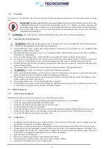
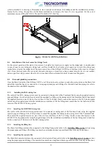
Fig. 8.6.4.1-1 - Filling the dosing system tank
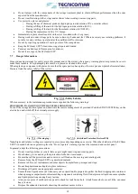
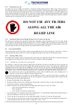
Fig. 8.6.4.1-2 - Empting the diaphragm pump
8.6.4.2
Installing the Sludge Discharge Valve (V2)
The Sludge Discharge Valve (V2) must be fixed on a stable wall, using the proper bolts (refer to attached G.A. drawings), as
near as possible to the ECOmar S Main Unit. Once fixed it has to be connected to the discharge of the Main Unit; to the sludge
tank (your supply) interposing a 3-way manual valve (your supply) for maintenance operation (refer to
SPECIAL
PROCEDURE
section); and to the inlet of the Multimedia inlet, using appropriate pipes and fittings (refer to attached G.A.
drawings for the identification of each valve interface; and to Flow and P&ID Diagrams for the piping sizing).
8.6.4.3
Installing the Multimedia Filter Station
The base frame of the Multimedia Filter Station must be fixed on a stable horizontal plane, using the proper bolts (refer to
attached G.A. Drawings). Once fastened the Multimedia Filter Station, you have to remove the manual multiport valve installed
on each of the tank that make up the system. Then pour on all the tanks of the first stage of the Multimedia Filter Station the
proper quantity of coarse quartzite and of Zeolite (for the correct quantity of fine Quartzite and Zeolite refer to the attached
Test Report). At this point, you have to pour (refer to the
MAINENACE INSTRUCTIONS
section)on all the tanks of the
first stage of the Multimedia Filter Station the proper quantity of coarse and fine Quartzite (for the correct quantity of coarse
and fine Quartzite refer to the attached TEST REPORT). After each tank is correctly filled, re-install the head valve, with all
the connected piping, on each tank. Finally the Multimedia Filter Station has to be connected to the clarified water outlet of
the Sludge Discharge Valve (V2); to the inlet of the U.V. Sterilization System; to a not-chlorinated fresh water supply (it is
advisable to interpose a two-way isolation valve); and to the untreated sewage outboard discharge, according to IMO/MARPOL
regulation (refer to the
SPECIAL PROCEDURES
section), or to the on board collecting tank, for the re-sending back of the
backwash waste water; using proper pipes and fittings (refer to attached G.A. drawings for the interfaces identification; and to
Flow and P&ID Diagrams for the piping sizing).
8.6.4.4
Installing the U.V. Sterilizer
Before fixing the base-frame of the U.V. Sterilizer on a stable horizontal plain, using the proper bolts (refer to attached G.A.
Drawings); check that there is enough space above it to allow easy extraction of the bulb and the quartz, and that there is
enough space to perform maintenance. The sterilizer must be positioned in an area protected against accidental splashes or
dripping condensation. Do not position the sterilizer in particularly damp and dusty environments.
Once the U.V. Sterilization System is well fixed, you have to connect it to the Multimedia Filter Station and to the discharge
line, using proper pipes and fittings (refer to attached G.A. drawings for the interfaces identification; and to Flow and P&ID
Diagrams for the piping sizing). It is recommended to install two cut-off valves, one at the inlet and the other at the outlet of
the system. We suggest also to install to install an anti-vibration joint at the inlet/outlet of the U.V. Sterilizing System, since
any vibrations on the pipes could cause breakage of the quartz tube and/or jeopardize the seal of the pressure nozzle. Flow rates
which cause pressure surges must be avoided at all cost.
WARNING:
Under no circumstances must the sterilizer be subject to mechanical stress from the pipes.
After completing the hydraulic connection, insert all the supplied quartz tubes into the U.V. sterilization chamber.
DANGER:
Quartz tubes are fragile and may cause serious injury when broken. Consequently they must be handled
with care, protecting the hands by wearing gloves that guarantee adequate protection.
Pay attention when inserting the tube to avoid accidental breakage. Lubricate the o-ring with Vaseline and position it outside
the. Insert the pressure nozzle and turn it clockwise without forcing it.
Caution
: sometimes the o-ring tends to stick to the outer surface of the tube.
Insert each supplied germicide U.V. lamp inside the corresponding protective quartz tube. Fit each quadripolar connector from
the electrical control panel of the U.V. Sterilizing System to the head of each U.V. lamp.


