30
8.8.2
H2O2 DOSING SYSTEM
The power supply for the H
2
O
2
dosing pump is normally (standard supply) sourced on from the plant Main Control Box and
the operator has only to connect the plug that comes from the dosing pump to the correct terminals of the ECOmar S main
control box (refer to attached Electrical Connections Diagrams).
This is valid only for the ECOmar S plant supplied with the standard (
1 Tank Control
) configuration. While, when the plant is
supplied with the
2 Tanks Control
configuration, on the rear side of the H
2
O
2
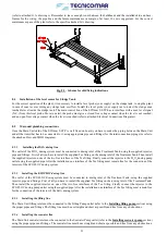
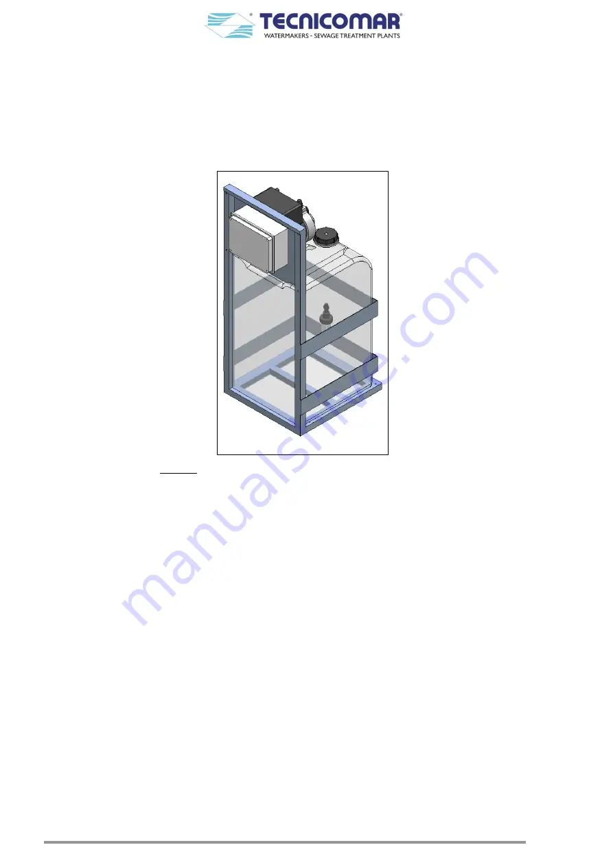
Dosing System (see figure below) there is an
electrical box, to be connected to the Main Control Box. Moreover, when the plant is supplied with the 2
Tanks Control
configuration for the 3 phases power supply, an auxiliary power supply 230 V AC (your supply) has also to be brought into
the electrical box of the H2O2 Dosing System (refer to attached Electrical Connections diagrams).
Fig 8.8.2 – H
2
O
2
dosing system for 2 Tanks Control configuration
In detail the box, installed on the rear side of the H
2
O
2
Dosing System when the plant is supplied with the
2 Tanks Control
configuration for the single-phase power supply, has to be connected to (refer to attached Electrical Connections Diagrams):
1.
Power Supply 230 V-AC from Main Control Box (supplied 3m cable FROR 3G1.5mm2);
2.
H2O2 Dosing Pump (supplied 3m cable FROR 3G1mm2);
3.
ECOFLOC Dosing Pump (supplied 3m cable FROR 3G1mm2);
4.
U.V. Sterilizer control box (supplied 3m cable FROR 3G1mm2);
5.
Starting signal for Dosing Pumps from Main Control Box (supplied 3m cable FROR 2x1mm2).
While, when the plant is supplied with the
2 Tanks Control
configuration for the three-phase power supply, the electrical box
of the H
2
O
2
Dosing System has to be connected to (refer to attached Electrical Connections Diagrams):
1.
External Power Supply (your supply) 230 V-AC (suggested cable FROR 3G1.5mm
2
);
2.
H
2
O
2
Dosing Pump (supplied 3m cable FROR 3G1mm
2
);
3.
ECOFLOC Dosing Pump (supplied 3m cable FROR 3G1mm
2
);
4.
U.V. Sterilizer control box (supplied 3m cable FROR 3G1mm
2
);
5.
Starting signal for Dosing Pumps from Main Control Box (supplied 3m cable FROR 2x1mm
2
).
8.8.3
LEVEL PROBE CONTROL BOX
The power supply 230 V AC of the Level Probe Control Box has to be brought from an external source (your supply), for any
ECOmar S configuration. The Level Probe Control Box has also to be connected to the Main Control Box and to the Level
Probe, installed on collecting tank. In particular, the electrical connections of the level probe control box are:
1.
External Power Supply 230 V-AC (supplied 3m cable FROR 2x1mm
2
);
2.
ECOmar S control box, installed on ECOmar S STP Main Unit (supplied 3m cable FROR 3x1mm
2
);
3.
Conductive level probe installed on sewage collecting tank (supplied 3m cable FROR 3x1mm
2
).
For the exact connections scheme of level probe control box, please refer to the annexed Electrical Connections Diagrams
.


