63
14.2.7
Macerating pump instructions
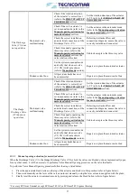
Periodically check that macerating pump works within its field of performance, and that absorbed current shown on nameplate
is not exceeded. After plant first start-up, inspections of macerating pump should take place monthly according use conditions.
Before any maintenance, disconnect the power supply and make sure the pump cannot be accidentally switched on.
WARNING:
When pump is not used, never forget liquid inside pump casing during cold weather!
Water may freeze and break the pump casing.
Each 3 months, if necessary, lubricate the mechanical seal. If after seal lubrication, the pump continues to leak replace the seal.
Each 6 months open the inspection cover or the casing and check inside. Remove possible foreign parts blocked inside the
casing. Flush the pump with clean water before draining. Clean the pump and the motor. If necessary, check more frequently.
Each 5-10 years make a general pump recondition.
ATTENTION
: Never run the pump dry. Start the pump only after filling completely with liquid. FILL THE PUMP
WITH LIQUID BEFORE STARTING. NEVER LET THE PUMP RUN DRY.
14.2.8
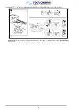
Three-Way Motorized Valves (V1&V2) instructions
It is recommended to periodically check each of the installed three-way motorized valves (V1 & V2), for any leaks or blockages
and repair them, if necessary. Moreover, it is advisable to periodically check the correct functioning of each valve.
If a three-way motorized valve does not work correctly, check:
•
The correct electrical connections between the valve and the main control box (refer to attached Electrical Drawings).
•
The motorized actuator of the valve is correctly set in the automatic mode.
•
The rotation direction of the valve is correctly set to Y2.
•
The valve and the connected pipe are clean and free from any blockage.
•
The electrical absorption of the valve to be below the max permitted absorption of the valve.
•
The electric continuity of the valve circuit for short circuit or coil interrupted.
If after performing all these checks the three-way motorized valve is still malfunctioning, it must be replaced.
14.2.9
Multimedia Filter Station instructions
While the ECOmar S STP is operating periodically check the reading value of the pressure gauge, installed on the Multimedia
Filter Station; if it is higher than the 30% of the value recorded during first start-up (refer to
FIRST START UP PROCEDURE
section) the Multimedia Filter Station needs that a backwash procedure is performed.
ATTENTION: Ensure to record the pressure gauge reading value (start-up pressure) during initial operation.
A periodic backwashing will prevent packing, reclassifying the Multimedia Filter Station bed and maintaining high flow rates.
If after performing a backwash procedure the Multimedia Filter Station does not restore its performance it may be necessary
to replace the media. The media replacement intervals depends on the incoming clarified water and on the flow that passes
through the Multimedia Filter Station.
To replace the Multimedia Filter Station content follow the procedures reported below.
MEDIA REMOVING PROCEDURE
Stop the water flow through the Multimedia Filter Station;
Prepare a container to collect the exhausted media;
Remove the manual multiport valve installed on the top of each tank that make up the system, together with all the
connected fittings;
Remove the media, inside each tank by scooping it out through the tank top port, vacuuming it out with a suitable wet/dry
shop vacuum or may be flushed out of the filter;
Rinse the internal piping, especially the top and the bottom diffuser, to remove any traces of media or dirty.
MEDIA FILLING PROCEDURE
Ensure that each filter is already empty and clean; and that the multiport valve, together with all the connected fittings are
removed from each tank;
Well clean the bottom and the top diffusers and make sure that they are free from scale, before refilling each tank;
Insert the bottom diffuser complete with the relative pipe inside each tank and center it, before adding any media;
Slowly pour the appropriate amount of coarse Quartzite into each tank;
Level the surface of the Quartzite;
Pour the appropriate amount of Zeolite into the tanks of the 1st stage;
Pour the appropriate amount of fine Quartzite into the tanks of the 2nd stage.
Wash away any media or dirt particles in the threads in the top of each tank.
Re-install the head valve, complete with the relative top diffuser and all the connected piping, on each tank, ensuring each
bottom diffuser pipe to the relative head multiport valve;


