background image


66 

14.4


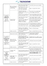
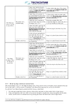
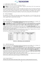
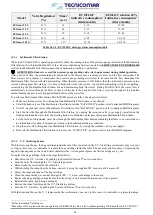
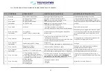
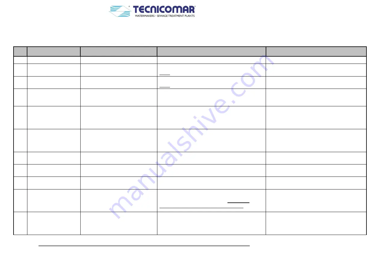
MAINTENANCE PLAN FOR SEWAGE TREATMENT PLANT ECOMAR S 

P/N  SCHEDULE 

COMPONENT 

MAINTENANCE ROUTINE 

WARNINGS IF NEGLECTED 

Every day 

The whole ECOmar S plant. 

System general check and inspection. 

Undetected malfunctioning could occur. 

Every day 


Hydrogen Peroxide tank; 


ECOFLOC tank. 

Check the level of the chemical products. 

Note:

 The level must never be below 10 cm. 

Undetected plant malfunctioning, due to H

2

O

2

ECOFLOC or both solutions missing, could occur. 

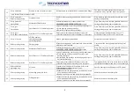
Every month / 
On condition 


Hydrogen Peroxide tank; 


ECOFLOC tank. 

Add chemical products if necessary. 

Note:

 The level must never be below 10 cm. 

Sewage treatment is NOT possible without chemical 
products. 

Every month 

Air intake 

• Check if air is released properly. 
• Check that air intake is not obstructed. 
• Check if exhaust pipe is straight in vertical dimension. 

Burst of the treatment tank. 

Every 1-2 months / 
On condition 

Level probe(s) 
(inside ECOmar S treatment tank) 

Uninstall and clean the floating probes, installed on 
treatment tank. 

Dirty probe gives no signal, so in case of no signal 
to the electronic card then the treatment tank might 
get overfull and liquids could escape from the air 
outlet. 

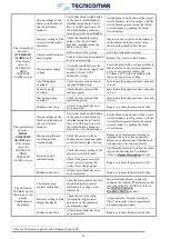
Every 2 months  

Dosing pumps 


Inspection of the suction ball check valve and 
discharge ball check valve. 


In case of obstruction clean the valves with fresh water. 


In case of corrosion replace the valves. 

Dosing pumps stop working and consequently the 
sewage does not get properly treated. 

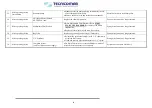
Every 3 months / 
On condition 

Stainless Steel and PVC fittings 


Inspection.  


In case of leakage tighten properly with dedicated tool. 

Leakages. 

Every 3 months 

Supplied Level Probes 
(inside collecting tank) 

Clean the contacts with abrasive paper. 

Probe may not work properly due to oxidation. 
Misleading or missing level signals. 

Every 3 months / 
On condition 

Sterilizer of U.V. Sterilizing System 

Empty the system radiation chamber, remove the quartz 
tube(s) and clean or replace quartz tube(s), if necessary. 

Undetected plant malfunctioning, due to U.V. 
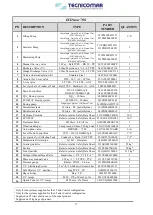
Sterilizing system out of service, could occur. 

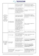
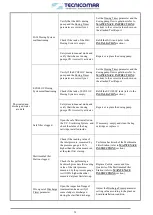
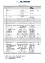
10 

Every 3-6 months  


3-Way Discharge Valve (V1) 
(controlled by motorized actuator); 


3-Way Sludge Discharge Valve (V2) 
(controlled by motorized actuator). 

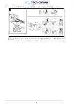
Check the correct activation / de-activation of 3-Way 
valve, without any blockage (refer to 

COMMON 

PROBLEMS AND TROUBLESHOOTING

 section). 

Correct system operation impossible in case of 
locked valves. Motorized actuators burn due to dirty 
gear. 

11 

Every 3-6 months 


Filling pump(s) 


Macerating pump 


Seawater pump 


Discharge pump

*


Check and, if needed, replace: 
- seal kits 
- impellers 

System does not work effectively. 

Summary of Contents for ECOmar 145 S

Page 1: ... TREATMENT MODEL ECOmar 20 S 32 S 45 S 70 S 145 S S Image for illustration purposes only Rev Date Main content revisions 00 10 02 2019 Main Unit H2O2 Dosing System Sea Water Pump Filling Pump H2O2 Dosing System ECOFLOC Dosing System Multimedia Filter Station UV Sterilization Unit Sludge Valve ...

Page 2: ... prevention standards described in this manual for damage due to the improper use of the equipment and for modifying it without the authorisation of Tecnicomar S P A Signs used throughout the Manual Warning These instructions should be followed carefully to operate the equipment correctly Danger These instructions should be followed carefully to avoid damage to the equipment or to the operator Not...

Page 3: ...rew 20 8 3 Fixing the skid 20 8 4 Installation of the level sensor for Sludge Tank 21 8 5 Main unit plumbing connections 21 8 5 1 Installing the H2O2 dosing line 21 8 5 2 Installing the ECOFLOC dosing line 21 8 5 3 Installing the filling line 21 8 5 4 Installing the seawater line 21 8 5 5 Installing the air relief 22 8 5 6 Installing the Main Unit and Sludge Discharge Valve V2 interconnection line...

Page 4: ...ation for motorized valves 57 14 MAINTENANCE INSTRUCTIONS 59 14 1 Ordinary Maintenance 59 14 1 1 H2O2 Dosing system 59 14 1 2 ECOFLOC Dosing system 59 14 1 3 Multimedia Filter Station 60 14 1 4 U V Sterilizing System 60 14 2 Extraordinary Maintenance 61 14 2 1 Collecting Tank level probes instructions 61 14 2 2 Filling pump instructions 61 14 2 3 Treatment Tank Level probes instructions 62 14 2 4 ...

Page 5: ...ing Do not store in direct sunlight Do not freeze see SPECIAL PROCEDURES section Do not store above 50 C 122 F Store only on base with arrows up 2 2 Unpacking a Open the wood case if any being careful to do not hit the protruding parts of the components such as fittings or pipes hose barbs flange etc b Use caution in moving the STP plant and all its loose parts with a forklift or a pallet truck af...

Page 6: ...ELECTRICAL CONSUMPTION OF THE UNIT 5 TREATMENT CAPACITY Marine Sanitation Device ECOmar20 S ECOmar 32 S ECOmar 45 S ECOmar 70 S ECOmar 145 S Average capacity per day lt 1500 2400 3375 5250 10875 Peak capacity per day lt 2000 3200 4500 7000 14500 Average capacity per hour lt 62 5 100 140 625 218 75 453 125 Peak capacity per hour lt 83 3 133 3 187 5 291 67 604 17 Sewage capacity treated per cycle lt...

Page 7: ... the diagrams above the system is composed by 1 A Main Unit Skid made by 1 1 A tank Treatment Tank made of PP polypropylene or SS stainless steel where the sewage water is treated 1 2 A pump Macerator or Macerating Pump to treat and discharge the treated water 1 3 A motorized Discharge Valve V1 to divert the treated water to the sludge discharge valve V2 inlet or back to the treatment tank 1 4 Lev...

Page 8: ...d H2O2 Dosing System and the ECOFLOC Dosing System at the same time If correctly installed and set refer to the INSTALLATION and to the System Settings sections the Disinfectant Liquid H2O2 Dosing System injects throughout the relative injector installed on the Treatment Tank a pre set quantity of H2O2 solution inside the tank to disinfect the water to be treated During the same time refer to the ...

Page 9: ... throughout the Multimedia Filter Station This component part of the Additional Unit mainly consists of two stages In the first stage the clarified water is treated by Zeolite to adjust its residual content In the second stage the clarified water is subjected to a filtration to eliminate any excessive presence of suspended solids Each of the Multimedia Filter Station stages consists of one or two ...

Page 10: ... an open free voltage contact signal to the ECOmar S main control box In this way the filling pump is still set in standby III When the sewage level of sewage reaches the maximum level the min level probe installed on the collecting tank has to continue to give an open free voltage contact signal to the ECOmar S control box and the max level sensor has to give a closed free voltage contact signal ...

Page 11: ...rods level probe supplied uncut and a level probe control box for the management of the level signals from the on board collecting tank your supply The 3 rods level probe is supplied uncut and must be cut according the collecting tank dimensions in a way to have that the rod related to the COMMON signal is the longer the one related to the min level signal is the medium rod and the rod related to ...

Page 12: ... the filling pump starts to transfer the sewage to the ECOmar S treatment tank up to the bottom sensor in the tank then stops transferring The monitoring of the absolute max level of the collecting tank by the level probe control box is available only if the plant is supplied with a 4 rods level probe In this case the rod related to the absolute max level must be cut in a way to be shorter than th...

Page 13: ...he careful reading of this manual by the installer is important for safety ends Nevertheless it must be considered that many of the arguments and information contained have a specialist attribute and need a more specific knowledge in the system electromechanical field to be understood For that reason the user should refer to a qualified technician for the installation and maintenance of the system...

Page 14: ...m sign of danger level warning and means that if the operations described are not well done they can cause heavy lesions death or long term risks for health The instructions should be followed carefully to avoid damage to the ECOmar S STP or to the operator CAUTION CAUTION sign means that if the operations described are not well done they can cause damage to the system and or to the operator NOTE ...

Page 15: ... Compliance The original copy of the CE Declaration of Compliance here reported in facsimile is delivered along with the test report of the ECOmar S plant in the annexes of this manual Fig 7 3 Declaration of CE Conformity form ...

Page 16: ...by the operator that is still responsible of the maintaining in good state of the system The validity and qualification of the maintenance operations are determinant factors for the system efficiency For that reason the maintenance must be adequate to avoid damage of the most stressed organs and to maintain a high system reliability 7 5 Safety Instructions and Prevention 7 5 1 Generalities The saf...

Page 17: ...e system or on any of its loose parts it is necessary to assure that it has been turned off and no one can accidentally change its configuration or turn it on When turned on the system presents moving parts pay attention to not approach the system with flapping objects smocks jackets ties chains bracelets etc The system produces noise the use of the headphones is necessary It is forbidden to turn ...

Page 18: ...g 7 7 1 Safety Labels Where necessary in the maintenance procedures are reported the following warnings PROCEDURE TO CARRY OUT WITH SYSTEM TURNED OFF Turn off the sewage treatment plant and deactivate the remote management if provided Push the STOP SYSTEM key on the electric box and switch off the external power supply Fig 7 7 2 Warning tag Fig 7 7 3 Individual Protection Devices IPD Note Signs an...

Page 19: ...otection Swelling of the external protection Parts of flexible tubes crushed Fittings moved Be sure that all the clamps protections and heat shields are well installed 7 9 Cuttings Prevention Adequately support components when working under them Stay away from moving and rotating parts let the protections installed until ready to perform the maintenance and reinstall them at the end 7 10 Fluid Rec...

Page 20: ...the inlet of the U V Sterilization System complete with the relative fittings and all the necessary accessories i Connection piping between the clarified water outlet of the Sludge Discharge Valve V2 and the inlet of the Multimedia Filter Station complete with the relative fittings and all the necessary accessories j Backwash Discharge outlet of the Multimedia Filter Station complete with the rela...

Page 21: ...et of the Treatment Tank using the supplied injector pipe and fittings First of all you have to install the supplied Tee fitting on the dosing inlet of the Treatment Tank Then install the supplied injector on one of the two free interfaces of the Tee fitting Finally connect the injector to the H2O2 dosing pump outlet using the supplied pipe After the installation one interface of the Tee fitting m...

Page 22: ... 8 6 1 1 Installing the Level Probe on the collecting tank The conductive 3 rods Level Probe standard supply matched with the Level Probe Control Box level probe represents an efficient solution for monitoring the level of liquids with a minimum conductivity value of 1mS and an easy installation and maintenance from the top of the tank The installation of the level sensor on the top of the collect...

Page 23: ...he size of the rods has to be taken including the thread of the plastic connector cap they are fixed in The rods are connected together passing through a blocking plate with three holes This plate needs to be repositioned and re fixed according to the new size with PVC sheath on each rod For the system supplied with 4 rods Level Probe follow the same sizing procedure as per the 3 rods Level Probe ...

Page 24: ...ge from the collecting tank should be fixed on a stable horizontal plane below the minimum level of collecting tank using the proper bolts refer to attached G A Drawings The plant filling pumps are not designed to treat sewage containing paper diapers or other similar On the collecting tank side pump suction side it is necessary to fit a manual ball valve not supplied using proper pipes and fittin...

Page 25: ...ly monitored by the board crew to prevent this to happen 8 6 2 Installing sea water pump The sea water pump should be fixed on a stable horizontal plain below the sea water line so that to avoid priming failures using the proper bolts refer to attached G A Drawings Remember that this pump is not self priming and that at first start up it is necessary to check the priming In case of problem we sugg...

Page 26: ... hydraulic connections are made refer to attached Flow and P ID Diagrams and to attached Electric Connections Diagrams it is possible to start the dosing pump Be sure that pump fill the pipe If the pipe is long and completely empty this should require some minutes 8 6 3 1 Transfer of H2O2 solution Before running the dosing system it necessary to fill the dosing system tank with the H2O2 solution P...

Page 27: ...ransfer of ECOFLOC solution Before running the dosing system it necessary to fill the dosing system tank with an ECOFLOC solution at 20 Proceed with caution using gloves and protecting glasses in order to avoid direct contact with the corrosive chemical refer to ECOFLOC Safety Data Sheet To fill the tank perform the following procedure Prepare the hand operated diaphragm pump Prepare a can with a ...

Page 28: ...r the re sending back of the backwash waste water using proper pipes and fittings refer to attached G A drawings for the interfaces identification and to Flow and P ID Diagrams for the piping sizing 8 6 4 4 Installing the U V Sterilizer Before fixing the base frame of the U V Sterilizer on a stable horizontal plain using the proper bolts refer to attached G A Drawings check that there is enough sp...

Page 29: ...onfiguration for the 3 phases power supply an auxiliary power supply 230 V AC your supply has to be brought into the Main Control box and connected refer to attached Electrical Connections diagrams to the proper terminals inside by a cable equivalent to those described in the table below We recommend to assign the power connections to skilled personnel and that the power supply line be disconnecte...

Page 30: ...lied 3m cable FROR 3G1mm2 3 ECOFLOC Dosing Pump supplied 3m cable FROR 3G1mm2 4 U V Sterilizer control box supplied 3m cable FROR 3G1mm2 5 Starting signal for Dosing Pumps from Main Control Box supplied 3m cable FROR 2x1mm2 While when the plant is supplied with the 2 Tanks Control configuration for the three phase power supply the electrical box of the H2O2 Dosing System has to be connected to ref...

Page 31: ...Omar S configuration using the appropriate electrical cable suggested FROR 2x1mm2 Moreover the supplied remote control has also to be connected to the Main Control Box using a proper electrical cable supplied standard 15m cable 4x0 5mm2 For the exact connections scheme of the supplied remote control please refer to the relative annexed Electrical Diagram 1 Power supply 230V AC 2 To ECOmar S contro...

Page 32: ...sioning or start up of the ECOmar S STP or to check the correct functioning of the main devices connected to the system in case of any system fault occurs 9 1 1 Programming the parameters of the Electronic board PRO14 02 for ECOmar S When the PCB Printed Circuit Board control panel is powered up it is possible to set the operational parameters of the plant The ECOmar S S T P is always supplied wit...

Page 33: ... do not change 07 Failure Delay sec allows to set a fault holding time after which each alarm is managed do not change 08 Discharge Valve V1 Delay sec allows to set the time necessary for the activation of the valve V1 do not change 09 Filling Failure Alarm min allows to set a filling time after which the Filling Alarm occurs do not change 10 Sea water Failure Alarm min allows to set a dilution ti...

Page 34: ...ys F1 AUTO and down F2 MAN Each status page is continuously and automatically updated in real time The first status page shows the activation status of filling macerating seawater and dosing pumps The second status page displays the activation status of discharge valve V1 and of second filling pump optional and two timers with countdown in real time The first timer is for the dosing pumps activati...

Page 35: ... filling pump starts The timer on the 3rd line is for the flocculation time and that on the last line shows the countdown for the sludge discharge time Once visualized the desired status informations to go back to the automatic mode menu push STOP ESC key More generally the STOP ESC key button can be used every time you need to delete an action or go back with the displayed screens To stop the pla...

Page 36: ...Sludge Tank Overflow Alarm Tank Overflow Alarm Overload Alarm and High Pressure Alarm The High Pressure Alarm is available only for the models supplied with the treatment tank in PP The Overload Alarm and the High Pressure Alarm are visualized by the same page 9 4 1 Filling Alarm If the filling pump does not transfer any liquid to the treatment tank or the minimum level of the treatment tank is no...

Page 37: ...ached Test Report the system will trip and on the display of the Main Control Box will appear the Seawater Alarm screen In case that a fault for Seawater Alarm occurs the plant display shows the following flashing screen Check the multilevel sensor ball type installed on Treatment Tank for any blockages or malfunctioning Then check that the seawater pump is running in the correct way without any b...

Page 38: ...ault for Tank Overflow Alarm occurs the plant display shows the following flashing screen Check the multilevel sensor ball type installed on Treatment Tank for any blockages or malfunctioning Verify that the liquid inside the Treatment Tank is above the Absolute Max level and empty the treatment tank refer to the SPECIAL PROCEDURES section resending the liquid back to the collecting tank or discha...

Page 39: ...SC key to return to system the main page Then restart the plant by pressing the START ENTER key the system will begin to run from the filling step if the liquid level inside the Treatment Tank is below the min level of multilevel sensor otherwise from the chemical dosing phase 9 4 6 High Pressure Alarm If the pressure inside the Treatment Tank rises above the set value refer to the attached Test R...

Page 40: ...rrect pressure value usually 0 2bar 10 Re install the pressure switch on the ECOmar S treatment tank Once the fault that has caused the alarm signaling is solved you can reset the alarm signaling by pressing the STOP ESC key At this point the alarm signaling will be reset and the display will show Press again the STOP ESC key to return to system the main page Then restart the plant by pressing the...

Page 41: ...e in manual mode the system can be run only from the main panel directly from the PC This remote control also allows to examine the system status pages 9 7 Remote control for ECOmar model Touch screen optional The remote control TOUCH SCREEN is available only when the automatic mode is active in manual mode the system can be run only from the Main Control Box The remote control allows to start and...

Page 42: ...RATION position refer to attached P ID diagram Connect all the require external power supply and check that the displays of the Main Control Box Level Probe Control Box and U V Sterilizer Control Box correctly lights on Verify that the Management system of the level signals from the collecting tank sensors is correctly installed and send the correct level signaling to the system Main Control Box S...

Page 43: ...e Main page section and restart the plant Otherwise if the Discharge Timer and Sludge Discharge Timer parameters need no adjustment ignore the previous step 10 2 Shutdown Procedure For a correct and safe system power off follow the SHUT DOWN steps listed below Push the STOP ESC key to stop the plant The ECOmar STP will switch from System Running to System not Running At this point you can push the...

Page 44: ...diagrams in the outboard discharge position 3 From the Manual mode page of the Main Control Box activate the filling pump refer to the Manual mode section 4 In case of systems provided with 2 Tanks Control configuration repeat all the steps for each filling pump otherwise for systems supplied with 1 Tank Control configuration ignore this step 5 Once the Collecting Tank your supply is empty stop th...

Page 45: ...45 12 1 1 Macerating Discharge pumps performance curves Fig 12 1 1 1 C30 50Hz performances ECOmar 20 32 S ...

Page 46: ...46 Fig 12 1 1 2 C30 60Hz performances ECOmar 20 32 S ...

Page 47: ...47 Fig 12 1 1 3 S42 50Hz performances ECOmar 45 70 145 S ...

Page 48: ...48 Fig 12 1 1 4 S42 60Hz performances ECOmar 45 70 145 S ...

Page 49: ...hree way ball valve H in to ECOmar S operation position refer to figure below and to attached flow diagrams 6 Press the STOP ESC key on the Main Control Box to return to the system main page 7 Reset the plant in automatic mode refer to the Manual mode section 8 To re start the system follow the evert day start up procedure refer to the ROUTINE OPERATION section Fig 12 2 Treatment Tank Emptying flo...

Page 50: ...the picture below of the Discharge Valve V1 and store it in a safe place at a temperature from 40 C to 80 C 14 If the temperature exceed 1 80 C range uninstall the pressure switch item C on the picture below installed on the treatment tank only for the plants with the tank in PP and store it in a safe place at a temperature from 1 C to 80 C 15 Fig 15 1 1 ECOmar S main unit 16 If the temperature ex...

Page 51: ...0 Make sure that a your supply 3 way ball valve H installed between the sludge discharge outlet of the Sludge Discharge Valve V2 and the inlet of the Sludge tank is correctly connected to the collecting tank or to an outboard discharge the untreated liquid can be discharged overboard only when permitted by the IMO MARPOL regulation 11 Set the 3 way ball valve H refer to the Emptying the treatment ...

Page 52: ...e of any leaks or restrictions on their suction piping and correct it Worn seals of any pump filling seawater macerating Replace pumps filling seawater macerating seals Air presence inside any plant circuit Check the presence of any air inlet all along the piping lines filling seawater sludge discharge clarified water discharge connected to system Pressurize the affected circuit filling seawater s...

Page 53: ...n control box The system shuts down for SLUDGE TANK OVERFLOW ALARM fault The display shows the SLUDGE TANK OVERFLOW ALARM screen Sludge Tank Overflow Check the liquid level inside the sludge collecting tank Empty the tank according the IMO MARPOL regulation Sludge tank level sensor your supply malfunctioning Check if the level sensor is correctly installed on the sludge tank and adequately connect...

Page 54: ...IGH PRESSURE ALARM fault The display shows the OVERLOAD HIGH PRESSURE ALARM screen Wrong settings of the black switch button of the circuit switch breakers Verify that black switch button of the circuit switch breakers installed inside Main Control Box is in OFF position with the switch button pushed out from the switch circuit breaker Set the black switch button of the circuit switch breakers in ...

Page 55: ... verifying that IN2 and IN5 are respectively 1 and 0 refer to Automatic mode section Repair or replace each supplied level probe control box Broken control box All previous checks have not been successful Repair or replace the main control box There is no or low flow throughout the clarified water outboard discharge Safe filter clogged Open the safe filter installed on the U V Sterilizing System a...

Page 56: ...et system in manual mode and verify that when set dosing pumps ON it correctly activates Repair or replace the dosing pump Safe filter clogged Open the safe filter installed on the U V Sterilizing System and check the status of the bag cartridge installed inside If necessary empty and clean the bag cartridge or replace it Multimedia Filter Station clogged Check if the reading value of the inlet pr...

Page 57: ...eck if the valve actuator is set in manual mode refer to the Manual opening activation for motorized valves section Set the actuator in the automatic mode refer to the Manual opening activation for motorized valves section Check the correct installation and electrical connections of the Discharge Valve V2 Referring to attached flow and connections diagrams ensure the valve is correctly installed a...

Page 58: ...ou can also operate on the lever while pressing the black button without blocking it refer to figure below Fig 13 1 1 1 Manual opening activation for motorized valves V1 V2 ECOmar 20 S 32 S 45 S 70 S 145 S ...

Page 59: ...lant operating without the addition of H2O2 solution because it will bring to a sewage treatment failure Sewage treatment is not possible without the addition of any of the two chemical solutions The H2O2 solution consumption depends on the system running period on the ECOmar S supplied model on the relative dosing pump flow regulation and on the setting value of the Dosing Timer parameter Here be...

Page 60: ...media Filter Station into BACKWASH position refer to attached P ID diagram Start the flow the through the Multimedia Filter Station by opening the isolation valve your supply installed on the fresh not chlorinated water inlet thus letting fresh not chlorinated water pass throughout Multimedia Filter Station Let the fresh not chlorinated water flow through the Multimedia Filter Station checking tha...

Page 61: ...rly clean the quartz To replace the U V lamps follow the steps listed below Shut down the U V sterilizer by pushing the System On Button on its control box Stop the water flow through the sterilizer Switch off the U V Sterilizer external power supply Remove the germicide lamp Drain the sterilization chamber by opening the drainage valve under the chamber Remove the quartz tube Clean the tube using...

Page 62: ...on could be caused by the wearing of the valves in which case they need to be replaced or by the clogging of the filter which then has to be cleaned It is suggested to periodically clean off the hydraulic parts valves and filter Periodically check the tank for any leakage or damage and repair or replace it if necessary Check the level of the chemical solution inside the tank and refill it before t...

Page 63: ...periodically check the reading value of the pressure gauge installed on the Multimedia Filter Station if it is higher than the 30 of the value recorded during first start up refer to FIRST START UP PROCEDURE section the Multimedia Filter Station needs that a backwash procedure is performed ATTENTION Ensure to record the pressure gauge reading value start up pressure during initial operation A peri...

Page 64: ...ontained in suspension in the water or incrustations due to the precipitation of salts may form on the quartz tube These deposits prevent the passage of the UV rays and reduce the performance of the system Therefore you must regularly clean the quartz It is not possible to indicate the frequency of cleaning This depends essentially on the quality of incoming water Should it become necessary to cle...

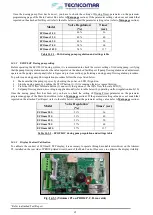
Page 65: ...ower by checking the power on LED 8 ignition Stop the dosing pump by pushing the STOP button 1 if it is running otherwise ignore this step Press the 100 flow full scale button 2 and verify the ignition of the 100 flow full scale LED 5 Set pump flow regulation according to supplied model refer to table below by operating on flow regulation knob 10 Once the dosing pump flow has been set you have to ...

Page 66: ...nspection of the suction ball check valve and discharge ball check valve In case of obstruction clean the valves with fresh water In case of corrosion replace the valves Dosing pumps stop working and consequently the sewage does not get properly treated 7 Every 3 months On condition Stainless Steel and PVC fittings Inspection In case of leakage tighten properly with dedicated tool Leakages 8 Every...

Page 67: ...ing pumps with clean fresh water stored in a different collection tank Corrosion of the dosing pumps and floating level probes 19 Before prolonged stop Multimedia Filter Station Perform a Backwash procedure refer to the MAINTENANCE INSTRUCTIONS section Dirty filter may cause bacteria growth bad odors during prolonged stop and or obstruction 20 Before prolonged stop Safe Filter of U V Sterilizing S...

Page 68: ...ART UP PROCEDURE section for the media stabilization Replace all the media in each tank if necessary Sewage treatment is no longer assured 28 After a prolonged stop Bag filter Replace bag cartridge and O ring s if necessary Sewage treatment is no longer assured 29 After a prolonged stop U V Sterilizer Reinstall the germicide lamp s in the U V chamber s or replace if necessary Clean and sanitise pi...

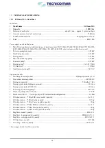
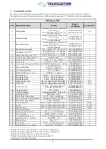
Page 69: ...zing chemical product Hydrogen peroxide 35 Flocculant chemical product ECOFLOC Dosing pump model 5 litres h at 7 Bar Dosing system tank Hydrogen peroxide 20 litres Dosing system tank ECOFLOC 10 litres Power supply of dosing pump 230 VAC Three way sludge valve V2 size 1 FFF Pressure switch 0 1 1 setting only on PP treatment tank configuration 0 2 Bar Filtration station 1st filter FBR vessel model q...

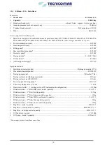
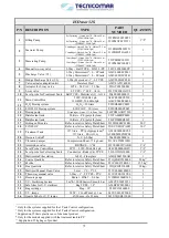
Page 70: ...product Hydrogen peroxide 35 Flocculant chemical product ECOFLOC Dosing pump model 5 litres h at 7 Bar Dosing system tank Hydrogen peroxide 20 litres Dosing system tank ECOFLOC 10 litres Power supply of dosing pump 230 VAC Three way sludge valve V2 size 1 FFF Pressure switch 0 1 1 setting only on PP treatment tank configuration 0 2 Bar Filtration station 1st filter FBR vessel model quantity 8 x 35...

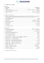
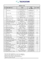
Page 71: ...ing chemical product Hydrogen peroxide 35 Flocculant chemical product ECOFLOC Dosing pump model 5 litres h at 7 Bar Dosing system tank Hydrogen peroxide 30 litres Dosing system tank ECOFLOC 10 litres Power supply of dosing pump 230 VAC Three way sludge valve V2 size 1 FFF Pressure switch 0 1 1 setting only on PP treatment tank configuration 0 2 Bar Filtration station 1st filter FBR vessel model qu...

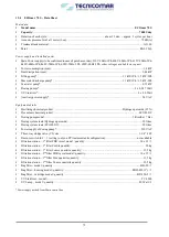
Page 72: ...roduct Hydrogen peroxide 35 Flocculant chemical product ECOFLOC Dosing pump model 5 litres h at 7 Bar Dosing system tank Hydrogen peroxide 30 litres Dosing system tank ECOFLOC 20 litres Power supply of dosing pump 230 VAC Three way sludge valve V2 size 1 1 4 FFF Pressure switch 0 1 1 setting only on PP treatment tank configuration not available Filtration station 1st filter FBR vessel model quanti...

Page 73: ... product Hydrogen peroxide 35 Flocculant chemical product ECOFLOC Dosing pump model 5 litres h at 7 Bar Dosing system tank Hydrogen peroxide 30 litres Dosing system tank ECOFLOC 20 litres Power supply of dosing pump 230 VAC Three way sludge valve V2 size 1 1 4 FFF Pressure switch 0 1 1 setting only on PP treatment tank configuration not available Filtration station 1st filter FBR vessel model quan...

Page 74: ...level 3 A316 204ES000000013 1 11 Main Control Box 230V 50 60Hz 1ph 230 400V 50 60Hz 3ph A24CE000EC0230 A24CE000EC0400 1 12 H2O2 Dosing system H2O2 20 liters 022SD000EC0032 1 13 ECOFLOC Dosing system ECOFLOC 10 liters 022SD000ECF045 1 14 Dosing pump Diaphragm Qmax 13 l h Pmax 7 bar 261PDMAAD57230 2 15 Disinfectant tank 20 liters PE polyethylene 261PD000SB0020 1 16 Disinfectant tank 10 liters PE pol...

Page 75: ...ng system H2O2 20 liters 022SD000EC0032 1 13 ECOFLOC Dosing system ECOFLOC 10 liters 022SD000ECF045 1 14 Dosing pump Diaphragm Qmax 13 l h Pmax 7 bar 261PDMAAD57230 2 15 Disinfectant tank 20 liters PE polyethylene 221TA000DP0020 1 16 Disinfectant tank 10 liters PE polyethylene 261PD000SB0010 1 17 Hydrogen Peroxide Refer to relative Safety Data Sheet 221LD000EC01KG 20 l 18 ECOFLOC Refer to relative...

Page 76: ...g system H2O2 30 liters 022SD000EC0145 1 13 ECOFLOC Dosing system ECOFLOC 10 liters 022SD000ECF045 1 14 Dosing pump Diaphragm Qmax 13 l h Pmax 7 bar 261PDMAAD57230 2 15 Disinfectant tank 30 liters PE polyethylene 261PD000SB0030 1 16 Disinfectant tank 10 liters PE polyethylene 261PD000SB0010 1 17 Hydrogen Peroxide Refer to relative Safety Data Sheet 221LD000EC01KG 30 l 18 ECOFLOC Refer to relative ...

Page 77: ...em H2O2 30 liters 022SD000EC0145 1 13 ECOFLOC Dosing system ECOFLOC 20 liters 022SD000ECF145 1 14 Dosing pump Diaphragm Qmax 13 l h Pmax 7 bar 261PDMAAD57230 2 15 Disinfectant tank 30 liters PE polyethylene 261PD000SB0030 1 16 Disinfectant tank 20 liters PE polyethylene 261PD000SB0010 1 17 Hydrogen Peroxide Refer to relative Safety Data Sheet 221LD000EC01KG 30 l 18 ECOFLOC Refer to relative Safety...

Page 78: ...em H2O2 30 liters 022SD000EC0145 1 13 ECOFLOC Dosing system ECOFLOC 20 liters 022SD000ECF145 1 14 Dosing pump Diaphragm Qmax 13 l h Pmax 7 bar 261PDMAAD57230 2 15 Disinfectant tank 30 liters PE polyethylene 261PD000SB0030 1 16 Disinfectant tank 20 liters PE polyethylene 261PD000SB0010 1 17 Hydrogen Peroxide Refer to relative Safety Data Sheet 221LD000EC01KG 30 l 18 ECOFLOC Refer to relative Safety...

Page 79: ...79 ...

Page 80: ...istributors and or at the Manufacturer s authorized technical service outlets in which case any of such costs and expenses shall be charged to the Buyer any transportation freight importation or insurance costs downtime costs etc The warranty of the replaced or repaired parts expires at the same time as the original warranty of the supplied Products No claim shall be considered and warranty shall ...

Page 81: ...INGS Connections to the black water collection tank s valves pipe size Connections to the filling pump s inlet outlet piping valves pipe size Connections to the sea water inlet outlet piping valves pipe size Connections to the sea water pump inlet outlet piping valves pipe size Connections to the sea water inlet device if supplied inlet outlet piping valves pipe size Connections to the outboard tr...

Page 82: ...______________ Correct wiring position at control box according to the Main power supply voltage Correct wiring position at seawater pump according to the power supply voltage Correct wiring position at seawater inlet device if supplied according to the power supply voltage Correct wiring position at filling pump 1 according to the power supply voltage Correct wiring position at filling pump 2 acc...

Page 83: ...p 1 checked YES NO Complete priming of the filling pump 1 checked YES NO if present Clockwise rotation of filling pump 2 checked YES NO in present Complete priming of the filling pump 2 checked YES NO Complete priming of the H2O2 dosing pump and check settings YES NO Complete priming of the ECOFLOC dosing pump and check settings YES NO Complete opening of sludge discharge valve V2 checked YES NO A...

Page 84: ... ________________________________________________________________________________________________ ________________________________________________________________________________________________ Installer Name in capitals and signature ______________________________________________ ______________________________________________ ...

Page 85: ...f printing Tecnicomar SpA reserves the right to make changes at any time without notice and without incurring any obligation whatsoever This Manual is intellectual property of Tecnicomar SpA Any reproduction of contents or drawings unless authorized by Tecnicomar SpA is not permitted and will be prosecuted ...

Page 86: ...e Quartzite Safety Data Sheet MAIN COMPONENTS PARTS LISTS FILLING PUMP Parts list exploded view SEAWATER PUMP Parts list exploded view MACERATING PUMP Parts list exploded view DOSING PUMP Parts list exploded view U V STERILIZER Parts list exploded view IMO MARPOL 227 CERTIFICATION Test Report Factory Acceptance Test Module B Certificate Declaration of Conformity with Module D Certificate Module D ...

Reviews: