9
floats on the liquid free surface. In the treatment process, can be released some vapors which, if not correctly expelled from
the treatment tank air vent, could bring to harmful overpressure inside the tank, damaging it. The Treatment Tank is designed
to withstand a certain degree of internal overpressure. In particular for the model with the tank in PP (polypropylene), on the
Treatment Tank is installed a
Pressure Switch
that stops the system leading it in Overpressure Alarm mode, in case of
overpressure inside the tank.
However, for a correct and safe operation of the ECOmar S STP it is recommended to connect
the Treatment Tank air vent as to have a vent piping (refer to the
INSTALLATION
section) free from any obstructions and
as straight as possible.
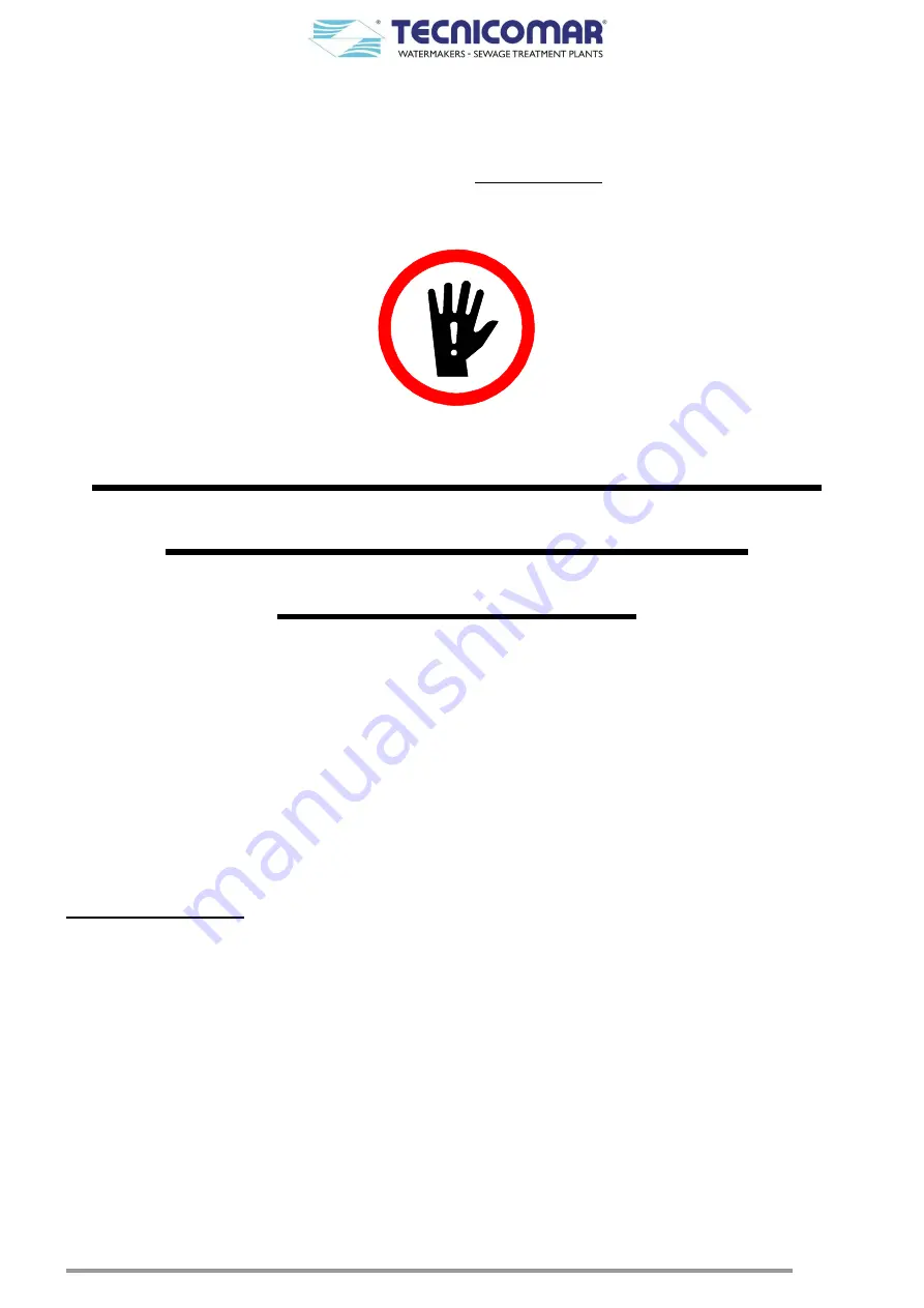
DO NOT USE ANY FILTERS
ALONG ALL THE AIR
RELIEF LINE
Once the treatment process is complete, stats the discharge phase. This phase begin is characterized by the status changing of
the
Discharge Valve (V1)
. This 3-way motorized valve, installed on the Main Unit, has in fact the task of diverting the flow
from the Macerating Pump to the Treatment Tank, during the treatment phase; or to the Main Unit discharge outlet, during the
discharge phase.
Moreover, the discharge phase mainly comprises two sub-steps: the clarified water discharge step and the sludge discharge
step. The discrimination between the two sub-steps is assigned to the
Sludge Discharge Valve (V2)
. This 3-way motorized
valve, part of the Additional Unit, has in fact the task of diverting the flow from the Main Unit discharge outlet to the inlet of
the Multimedia Filter Station, during the clarified water discharge step; or to the on board sludge tank (your supply), during
the sludge discharge step.
During the clarified water discharge step the water pass first throughout the
Multimedia Filter Station
. This component, part
of the Additional Unit, mainly consists of two stages. In the first stage the clarified water is treated by Zeolite to adjust its
residual content. In the second stage the clarified water is subjected to a filtration to eliminate any excessive presence of
suspended solids. Each of the Multimedia Filter Station stages consists of one or two filter that can be backwashed (refer to
SPECIAL PROCEDURES
section) using fresh not-chlorinated water (your supply).
At least the clarified water pass throughout the
U.V. Sterilizer
, which ensure the bacterial removal from the treated water, just
before been discharged. This U.V. Sterilizer is supplied complete with a bag filter, which as the task to protect the U.V. lamps
from the presence of any gross particles. Moreover, an anti-siphon valve set is also supplied for the outboard discharge, in case
of discharge under the seawater line, to prevent siphoning on the outboard discharge line.
6.1
Management system of the level signals from the collecting tank sensors
The main control box of the ECOmar S STP has to interface with a min level signal (N.C.) and max level signal (N.O.) from
the level probes installed on the sewage collecting tank (your supply). The system does not manage the signal for the absolute
max level of the collecting tank. This signal (if provided by the installed probe) can only be used for local or remote signaling.
This signals can be derived from the level probe control box (standard supply), from a junction box connected with two or
three lateral level probe (supplied on request), or from any other levels detecting system (your supply), capable of sending the
correct level signals, as above specified, to the system control box.
When the system is correctly connected to the level sensors of the on board collecting tank and the level probes are configured
to give the correct signals to the system control box; the ECOmar S plant will operate as described below:


