background image

3.  IMPIANTO TIPICO – TYPICAL SYSTEM LAYOUT – INSTALLATION TYPIQUE 


· 

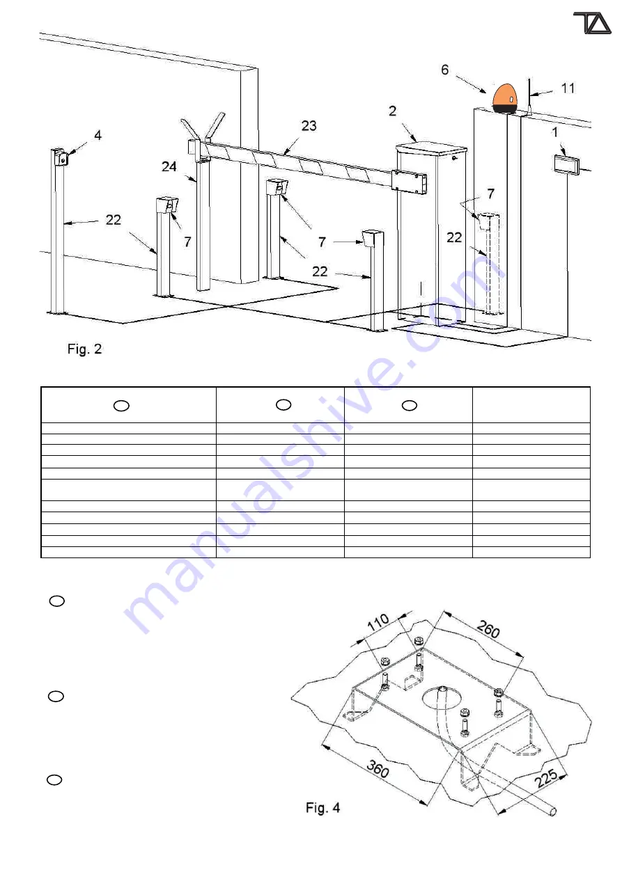
Componente impianto - Component - Composant


N° FILI x SEZIONE 

N° WIRES x SECTION 

N° CABLES x SECTION


1)

Interruttore di linea alimentazione 

Power supply switch 

Interructeur general 

2)

Barriera 

Barrier 

Barriere 

4)

Selettore a chiave 

Key switch 

Selecteur a clef 

2 x 1 

6)

Lampeggiante 

Signal clinking 

Clignotant 

2 x 1,5 

7) 

Fotocellula 

Photocells 

Cellules photo 

RX    4 x 0,5 

TX    2 x 0,5 


11) 

Antenna 

Aerial 

Antenne 

RG S8 

22) 

Pilastrino 

Pillar 

Potelets 


23) 

Asta in alluminio 

Aluminium arm 

Lisse en aluminium 


24)

Appoggio fisso per asta 

Arm support 

Support lyre 


GB


6.  INSTALLAZIONE E MESSA IN FUNZIONE – INSTALLATION – INSTALLATION MESSE EN FONCTION 


1) 


GB 

Realizzare una piazzola in calcestruzzo di 

dimensioni minime di base 500x500 mm e 500 mm di 
profondità su cui poter fissare l'armadio barra. La 
superficie della piazzola deve essere perfettamente in 
bolla. Al centro della piazzola bisogna prevedere uno o più 
cavidotti per il passaggio dei cavi elettrici. Se la barra è 
dotata della base a murare (pos.44) annegare la stessa 
nella piazzola (fig. 4).


Build a platform in cement of least dimensions with 

base 500x500 mms and 500 mms of depth on which it will 
be able to fix the barrier. The surface of the platform has to 
perfectly be in bead. In the center of the platform it needs 
to foresee one or more pipeline for the passage of the 
electric cables. If the barrier is equipped with foundation 
plate (pos.44),  drown the same one in the platform (fig. 4).


Réaliser une place en béton de dimensions 

moindres de base 500x500 mm et 500 mm de profondeur 
sur laquelle pouvoir fixer l'armoire barriere. La surface de 
la place doit être parfaitement en bulle. Au centre de la 
place il faut prévoir une ou plus de canalisations pour le 
passage des câbles électriques. Si la barriere est douée 
de la plaque de scellement (pos.44) noyer la même dans 
la place (fig. 4).

T.A. Tecno Automazione s.r.l.

 - Via Vicinale snc - 03018 - Paliano - (FR) - Italy - Tel +39 0775 533677 - Fax +39 0775 533299 - info@tecnoautomazione.com - 

www.tecnoautomation.com 

-

 www.tecnoautomazione.com

Summary of Contents for PK 3 Series

Page 1: ...WAYS CONTROLLING ACCESS BARRIERES DE BARRAGE DES PASSAGES VEHICULES CONTROLE ACCES BARRIERE PER SOLO USO VEICOLARE ONLY VEHICULAR ACCESS BARRIERS BARRIÈRES SEULEMENT POUR USAGE VÉHICULER PK Series T A Tecno Automazione s r l Via Vicinale snc 03018 Paliano FR Italy Tel 39 0775 533677 Fax 39 0775 533299 info tecnoautomazione com www tecnoautomation com www tecnoautomazione com ...

Page 2: ...t and must be kept out of the reach of children for whom they may be a source of danger Before beginning the installation check that the product is in perfect condition Do not install the product in explosive areas and atmospheres the presence of flammable gas or fumes represents a serious threat to safety Before installing the motorisation device make all the structural modifications necessary in o...

Page 3: ...ezza per comando manuale con manovella Finecorsa elettrico di apertura e chiusura registrabile e collegato alla centrale di comando Finecorsa meccanico di apertura e chiusura incorporato e registrabile Centrale elettronica di comando incorporata e precablata Electrowelded steel support frame Panels in 12 10 prep ainted aluminium Locking cover for access to emergency manual command Anodized alumini...

Page 4: ...gna prevedere uno o più cavidotti per il passaggio dei cavi elettrici Se la barra è dotata della base a murare pos 44 annegare la stessa nella piazzola fig 4 Build a platform in cement of least dimensions with base 500x500 mms and 500 mms of depth on which it will be able to fix the barrier The surface of the platform has to perfectly be in bead In the center of the platform it needs to foresee one ...

Page 5: ... sur la base avec les dés en dotation Attention pour accéder au fond de l armoire barriere il faut ouvrir le couvercle noir pos 42 en débloquant la serrure pos 34 et ôter vers le haut le panneau latéral en aluminium sur le côté opposé à celui de sortie de l arbre portant la lisse fig 5 Azionare manualmente la vite pos 60 vedi cap 10 esploso componenti con la maniglia pos 43 finchè la ganascia porta ...

Page 6: ...s commandements et des accessoires à la platine pos 134 voir chap 10 explosé composantes en suivant les normes en vigeur Relier à masse Pour les connexions électriques à la platine et pour eventuelles programmations et ou régulations utiliser les instructions de connexion au trousseau de la même Le fin de course pos 69 bloque le fonctionnement électrique à couvercle ouverte L eventuale regolazione ...

Page 7: ...ale qualificato Ruotare la PIASTRA SUPPORTO CENTRALE di 180 in modo da poter intervenire sul lato opposto a quello attuale Smontare la ganascia porta asta pos 66 fig 6 fissata all albero di manovra e riposizionarla sul lato opposto dell albero di manovra previo smontaggio del tappo in plastica di colore nero che andrà a chiudere il foro lasciato libero sul lato opposto Attenzione il serraggio della v...

Page 8: ...y sense or counterclockwise to enliven the arm in the 2 senses Completed the manual manoeuvre the handle must be replaced in its center see fig 10 and close again the cover with the key Warning when the cover is open is not possible for safety the motorized command of the barrier since the safety limitswitch pos 69 is activated En cas de black out ou de panne pour actionner manuellement la barrière...

Page 9: ... remote control or the key switch the barrier doesn t open Emergency STOP activated Check possible switches or command After a command with the remote control the barrier doesn t open but the key switch works The remote control has not been memorized or it is damaged or the battery is low Memorize the remote control in the unit or replace the battery N B If the failure remains please contact your ...

Page 10: ...ral periodic control of the corrected operation of the eventual safety edge applied on the inferior side of the arm 4 Semestral periodic control of eventual other devices of protection installs to you 5 Semestral periodic control of the corrected operation of the electromechanical limitswitches 6 Semestral periodic control of the main devices push button radio devices etc 7 Semestral periodic cont...

Page 11: ...TAILED DESIGN OF ALL THE SPARE DETAIL ECLATE T A Tecno Automazione s r l Via Vicinale snc 03018 Paliano FR Italy Tel 39 0775 533677 Fax 39 0775 533299 info tecnoautomazione com www tecnoautomation com www tecnoautomazione com ...

Page 12: ...mit switch cover Fin de course capot stop 70 Molla di bilanciamento Spring Ressort 71 AF062F 1 Tappo nero Ø80x1 5 Black plug Bouchon noir 72 AF015F 4 Tappo 40x30 Plug Bouchon 73 1 Asta alluminio anodizzato 80x30x2 Galvanized aluminium arm Lisse alumin 74 SC6 20 1 Linguetta 6x6x20 Forma A UNI 6604 Tab Patte 75 AF018F Strisce rosse rinfrangenti Red reflective bands Bandes réfléchissantes rouges 76 B10...

Page 13: ...215 mm 230 mm n 1 MTK85Z n 1 MTK25Z 185 mm 215 mm PK 3 Asta Arm Lisse 80x20x1 2 Lung Asta Lenght arm Long lisse Tipo molla Type spring Type ressort 2 5 N 1 MTK5F For private households Informa on on Disposal for Users of WEEE This symbol on the product s and or accompanying documents means that used electrical and electronicequipment WEEE should not be mixed with general household waste For proper...

Page 14: ...ture ele riche ed ele roniche RAEE Il simbolo del cassone o barrato riportato sull apparecchiatura o sulla sua confezione indica che il prodo o alla fine della propria vita u le deve essere raccolto separatamente dagli altri rifiu per perme erne un adeguato tra amento e riciclo L utente dovrà pertanto conferire gratuitamente l apparecchiatura giunta a fine vita agli idonei centri comunali di raccolta...

Reviews: