IST-293.IM01.01
Istruzione / User’s Manual / Manuel d’utilisation
Pag.5/10
TECNOCONTROL s.p.a:Via Miglioli 97 SEGRATE ( MI )ITALY
Tel. +39 02 26922890 - Fax +39 02 2133734
communication or uncorrected) please replace with new one.
3)
If a new
“
Cartridge Sensor
” is installed, or it is not
correctly connected or a not compatible one is mounted. Please check the cartridge connections and compatibility
(
see on page 1
) these checks are made connecting and disconnecting the device. If the condition does not change,
please replace the unit and/or send it back to the supplier to repair.
Yellow and green LED activates (
0mA output signal
):
this happens when the “
Cartridge Sensor
” is not working. First
try to disconnect and connect the unit, finally try to replace a new
“
Cartridge Sensor
”. If the condition is not change,
please replace the unit and/or send it back to the supplier to repair.
INSTALLATION
The gas detector must be accurately installed and testing according to the national dispositions in force on the
safety of the plants and installation of electric devices in areas with danger of explosion.
Mounting
: The
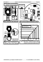
Fig. 2
shows the instrument size. The unit must be positioned vertically with the sensor downwards.
Models TS293IM
should be fixed at 20-30 cm from the ceiling (Methane is lighter than air).
Model TS293IG
should be fixed at 20-30 cm from the floor (LPG gas is heavier than air).
Electrical Connection (
see Fig.2
)
: the maximum distance to install each detector from the Gas Central Unit is show
in
table 1
. Normally use a tree wire shielded cable.
The terminals (
+ - S
), are polarized plug-in type, it is necessary to extract them to make the connection.
Note: Dip-Switch should be set with instrument powered off. Dip-Switch 1 settled ON activates ALARM
Red LED indication (see Table 2).
Important
:
after installing,
power up the unit.
It is not necessary perform any adjustment,
wait about 20 to 30 min-
utes and then,
if it is required
,
carry out the "
Operation Check
"
(
see ‘
Test and Calibration
).
COMPATIBILITY WITH OTHER CENTRAL UNITS:
In case of a central unit other then Tecnocontrol,
please verify
the max load resistor as shown in
Fig. 4
. We suggest using 24Vdc power supply.
WARNING
Average life
: The sensitive element used in this detector has an excellent stability in time. In fresh air and in nor-
mal working condition the sensor's life is about 5 years from the date of installation. After this period the yellow LED
“
FAULT
” flashes every 3 seconds, is necessary replacing the “
Cartridge Sensor
”.
Periodical testing
: depending on the use, we advise to carry out working tests every 6÷12 months. Tests, Zero
Adjust and Calibration with Gas/Air mixture as explained in chapter “
Tests and Calibration
”.
Note:
the detector is not able to detect gas leaks occurring outside the room where it is installed, neither inside
walls or under the floor.
Warning:
Consider that in polluted environments, with the continued presence of vapours of flammable gases or
over the standard temperature and pressure, the useful life of the sensor can be reduced.
The NDIR sensor used in the models TS293 / IM and / IG is not able to detect Acetylene and Hydrogen. To detect
acetylene must be required TS293IE model.
TEST and CALIBRATION
PAY ATTENTION
:
following tasks should be performed with attention and by competent and trained per-
sonnel; because starting this procedure it will cause the activation of connected alarm devices.
Operation Check, Zero Adjust and Calibration
:
are different code protected functions. To access these functions
is necessary to insert the relevant “
Code
" through the keys F1 and F2. To have the key pressure recognized, hold
pressing it for around a second (
until the Green LED doesn't switch off for a moment
). Then the next key can be pressed. In
case of error all it takes is waiting around 10 seconds and the sequence is automatically erased.
Calibration Kit, Sample Gas Cylinders
(
for Calibration Check and Calibration
) please, only use a mixture:
MODEL
Sample Gas Cylinder for Calibration
Tecnocontrol Code
TS293IM
2.2% Volume
(= 50% LEL)
Methane
(CH
4
)
in air
Available on request
TS293IG
0.7% Volume
(= 50% LIE)
Butane
(C
4
H
10
)
in air
Available on request
You can use
disposable cylinder, complete with adjust valve
. Is also necessary to use
the calibration kit
Tecnocontrol model TC011
(
for non-corrosive gases
) or
TC014
(
Stainless steel
).
“INSTRUMENT OPERATION CHECK” (
Check Code
: F2, F2, F1, F1)
:
this function allows to effect a functional test
of the equipment. After having inserted the "
Check Code
", all LEDs are switched off. Then LEDs will switch on in se-
quence, from the yellow up to the red. At the end all the LEDs will remain lighted for around 5 seconds, and then
the detector returns at the conditions of normal operation. It is advisable to perform this operation every 12 months
according to the use.
Note
: this function is not working if the red LED is already switched on.
“ZERO ADJUST” (
Zero Code
: F2, F1, F1, F2)
:
this function is to adjust the Zero sensor and can be done in clean
air only (environment without the presence of gas or other pollutants). Consider that the TS293I has a sophisticated
follower of zero, that every hour will reset the sensor, if of course there is the presence of gas. If necessary, per-
form this operation after installation or after changing the “
Cartridge
” or every 6-12 months depending on environ-
mental conditions. After entering the "
Zero Code
" as confirmation of the operation, there will be a flashing red LED
and output becomes 4.0 mA.
Note
: This function is not working if mA output is more than
5,6mA (10% LEL)
and/or red or yellow LED is already
been switched on. In this case, it will be necessary to recalibrate the unit and/or replacing the “
Cartridge
”.
“
CALIBRATION” (
Calibration Code: F2, F2, F2, F1, F2, F2
):
this function allows completely recalibrate the sensor using
the gas mixture indicated above.


