

Code
A
B
C
Weight Kg
PTR 02/130
230
130
115
2,5
PTR 02/180
230
180
115
2,6
3.5 SHIELD MATERIAL
LEXAN® POLYCARBONATE
: it is a compact POLYCARBONATE plate (PC), transparent and colourless,
highly impact and bending-proof and quite abrasion-proof, mechanical characteristics that make this material
ideal to be used as protection shield against accidental impacts.
LEXAN® POLYCARBONATE has therefore an actual resistance higher than any other similar plastic material:
- in transportation and handling.
- in all working phases.
- in assembly.
- in the final use.
LEXAN® POLYCARBONATE includes the positive characteristics of many plastic materials, but its mechanical
characteristics can be impaired when coming into contact with certain chemical products, such as common
solvents, highly alkaline products and certain lubricant-coolants, and anyway with all the substances which
contain typically aggressive agents against the PC.
3.6 REFERENCE DIRECTIVES AND REGULATIONS
The protection device has been created in conformity with Community directives and European harmonizing
regulations pertaining to machines and in particular:
3.0 DESCRIPTION OF THE SAFETY COMPONENT
3.1 CHOOSING THE SAFETY COMPONENT
The safety component
PTR 02/…
is available with various-size shield,
PHOTO 2
.
Select the correct size, according to the characteristics and dimensions of the machine:
- First check the general dimensions of the machine, considering that, on a generous size
machine, it is possible to work both small and big pieces, therefore the component must be
chosen considering the highest potential of the machine, and in relation to the type of working
that the machinery must be equipped for.
- Opt for the most suitable guard size, considering a safety distance to be kept between the
protection shield and the spindle, including the tool being used and any shavings which might
be dragged during working.
3.2 CONDITION OF SUPPLY
PHOTO 1
- Regardless of the quantity of safety components purchased, the general package
is in any case in the form of one or more robust cardboard boxes, containing the various single
packages, well protected from each other with suitable material (cardboard and expanded
polystyrene plugs).
The safety device
PTR 02/...
is supplied pre-assembled in some groups, contained in
appropriate polyethylene cases
1D
, the assembly screws are contained in a small case
1F
.
All the packages are marked with an external identification label
1G
, bearing the data of the
article purchased and with relevant progressive numbering; the same label is also on the
back of this user manual.
3.3 TECHNICAL INFORMATION 3.4 WEIGHTS AND DIMENSIONS
4.0 INSTALLATION
4.1 ASSEMBLING THE SAFETY COMPONENT
1 -
PHOTO 1
- The safety component is simply assembled by joining the three groups, using
the nuts and bolts supplied.
Assemble the shield
1E
, inserting its clamp
1D
through the hexagonal rod
1C
.
2 - then install the angular anchor stirrup
1A
on the body of the micro-switch box
1B
.
Note:
the clamp
1D
has a particular seat for the connection of the support hexagonal rod, this
allows different radial positions of the shield, with an offset of 60° from the box group
1B
,
which in turn can be anchored to the machine in different positions.
The most common and used position is shown in
PHOTO 4
.
Note:
The
PTR 02/...
series guards are assembled by the company in the standard
configuration for the installation on the left side of the machine, as in the case of most Drills. If
necessary, it is possible to reverse the guard assembly side, from left to right, by simply
intervening on the reversibility of the components forming the microswitch box
1B
.
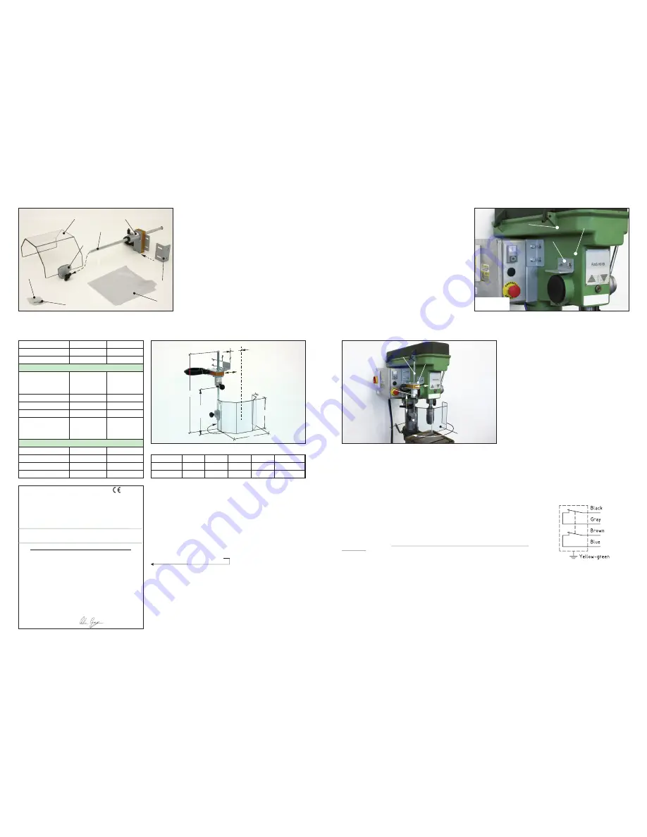
4.2 ANCHORING THE SAFETY COMPONENT
3 -
PHOTO 3
- Bring the complete component near the anchor area, putting the angular
anchor stirrup
3A
to contact with the head of the machine
3B
, identify the most suitable
position, so that it does not interfere with the controls of the machine and the normal working
maneuvers – it must further allow: a safe drilling-threading of the base, preventing any
damage to the internal parts, (gearbox, spindle tube, etc.) - a sufficient travel of the shield-rod
group without any limitations due to the interference with the speed change casing
3C
- a
satisfactory horizontal ”centring” with the spindle axis.
4 - For a final identification of the ideal anchor point, further consider that: the presence of any interferences between the guard and small parts or irregularities of the base can be prevented with the help of an
adjustment plate (not supplied).
5 - Once the ideal position has been identified, ”mark” the two holes present on the angular anchor stirrup
3A
, using a common marking-off tool.
With a suitable drill, make two Ø 6.7 holes to be threaded M8 and deep enough for the length of the screws supplied - no. 2 TE 8x20.
4.3 ADJUSTING THE SAFETY COMPONENT
6 -
PHOTO 4
- Once the guard has been anchored to the machine, proceed with the horizontal
adjustment present on the slotted anchor stirrup
4A
, so that the shield middle is on the spindle
axis.
7 - Proceed with the vertical adjustment of the shield, in relation to the work field to be
”segregated”, two ways are possible to prevent any ”interferences” due to the working in
progress:
A= Adjust the shield
4C
on its support rod
4B
through the clamp
4D
.
B= Adjust the shield-rod group
4C
+
4B
through the microswitch box
4A
.
8 – To prevent the shield from opening spontaneously during working, act on the “friction”
register
4E
.
Note: The protection shield
4C
is made of shock proof plastic material, it can be suitably
shaped, for any interferences with the equipment present in its field of action (e.g. piece
locking vice).
4.4 ELECTRIC CONNECTION OF THE SAFETY INTERLOCK TO THE MACHINE
The electric connection of the safety interlock to the machine requires the intervention of skilled and authorized personnel, familiar with the
main safety machinery standards.
- Make sure that the machine is preset for interfacing the safety consents envisaged; consult (if present) the instruction manual supplied by
the original constructor of the machine.
- The
PTR 02/...
series guards are provided with a safety switch, equipped with n.2 NC contacts (normally closed) as per norm EN 60947-5-
1, and they have an electric pre-wired wire, protected by special sheath.
- The electric wires coming from the guard must be connected to the safety circuit of the machine which cuts off the control on the movement
of the spindle.
- The protection sheath of the electric wire must be kept for its whole length, up to the wire input into the electric board of the machine.
- Protection from short-circuit of the electric interlock must be must be guaranteed by an anti-overcurrent device, as shown in sheet 3.3
TECHNICAL INFORMATION.
The devices are thus ready to be connected to a control and safety circuit with “expected architecture” of cat.3 pursuant to EN ISO 13849-1.
The closure of the interlocked guard
must not restart the spindle rotation, this must be started manually through a control provided
for this purpose.
4.5 VERIFYING THE OPERATION
Once the mechanical assembly of the guard and its electric connection to the safety circuit of the machine have been completed, it is necessary to check the proper operation of the whole, as follows:
1 - It must be only possible to operate the spindle motor with the guard in closing position, (therefore in the position shown in
PHOTO 4
).
2 - On the contrary, when opening the guard, the spindle motor must stop immediately and its restart must necessarily require a sequence of guard repositioning and motor start through voluntary maneuver, by special
control provided for this purpose.
1D
1D
1A
1E
1B
1C
1F
1G
PHOTO 1
1D
1D
1A
1E
1B
1C
1F
1G
PHOTO 1
A
B
C
80
40
20-
70
S
p
in
d
le
A
x
is
450
170 -
430
PHOTO 2
3
2
MM.
DIN 53455 N/mm
²
DIN 53452 N/mm
²
DIN 53457 N/mm
²
4
>
70
2500
100
Thickness used
Module strength
Ultimate tensile strength
Bending strength
Unit of measurem.
Values
Level of protection
IP 67
- 5°C + 45°C
Working temperature
°C
Type of electric contacts
Nr
Ui
gG type fuse
2 NC
400V
10A
Nominal insulation voltage
Short circuit protection
Interrupted current
(nominal capacity contacts)
Mechanical duration of safety
switch with suitable greasing
of the piston head
Cycles of maneuver
1 Million
Category of use:
DC13
AC15
24V - 2A - 125V - 0,4A
250V - 0,3A
24V-4A / 120-250V-4A
400V - 3A
Caratteristiche dello schermo di protezione trasparente
Characteristics
Accord. to IEC/EN 60529
i
Electric safety switch characteristics
Characteristics of the transparent Shield
3A
3B
3C
PHOTO 3
Second Attachment IIC of 2006/42/EC
The manufacturer:
Tecno Più S.r.l.
Via O. Respighi 56/6 – 47841 – Cattolica (RN) Italy
DECLARES ON HIS OWN AND EXCLUSIVE RESPONSIBILITY
T
hat the safety components that do not enter into attachment iv of 2006/42/EC
put onto the market separately and identified as:
Type: PTR 02/130 - PTR 02/180
Safety function performed :
I
Year of construction
:
2011
Are in conformity with what is envisaged by the inherent Community directives:
- 2006/42/EC
relative to machines
- 2006/95/EC
relative to safety of the electric material
And have been, in addition, respected as far as the following harmonized regulations are
applicable:
- UNI EN 1088:2008:
Safety of the machinery - Interlocking devices associated with safety
guards – Principles of design and choice.
- UNI EN 953:2009:
Safety of the machinery - safety guards - General Requisites for the
design and construction of fixed and mobile safety guards.
- CEI EN 60947-5-1
e
IEC 947-5-1:
Low voltage equipment.
Devices for control circuits and maneuver elements - Electromechanical devices for control
circuits.
CEI EN 60204-1:
Safety of the machinery. Electric equipment of the machines.
Part 1: General rules.
nterlocked Safety Guard for pillar Drill and radial Drill
DECLARATION OF CONFORMITY
Tecno Più S.r.l.
The legal representative
Signature...
Palazzi Giuseppe
............................................
Date:
Cattolica
4D
PHOTO 4
4A
4E
4B
4C
ELECTRIC CIRCUIT
Microswitch with n.2 NC contacts


