I.T.S. Ital Trade Services PT 630 Operating Manual
10
10
10
10
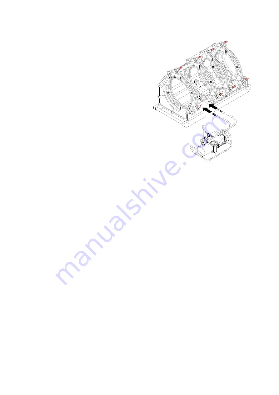
2.4.2 How to use the hydraulic unit
Operating Instructions
In order to make easy the learning we shall proceed to the description step by
step of all operations need in order to complete a welding according to the
following description:
Important !
Before begin the following operation be sure that:
- The lever
A
is fixed into the special housing
- Substitute the metal plug with the plastic black and red plug the
plastic plug is supplied with the machine into a plastic bag.
01.
Fit the two pipes to be weld ( see relative instructions )
02.
By turning the lever
E
anticlockwise bring the pressure to zero,
checking the pressure gauge
D
03.
Turn clockwise the lever
E
until closing ( please avoid using an
excessive strength )
04.
Bring the lever
A
into position
A3
05.
By turning clockwise the hand wheel
F
achieve the inertial pressure
value ( value of pressure need in order to allow the trolley moving )
note the value of inertial pressure read into the pressure gauge
D
,
then by still operating the hand wheel
F
, increase the inertial pressure
value by the welding theoretical pressure value as per attached table.
06.
Achieved the true welding pressure value ( inertial pressure plus
theoretical welding pressure ) bring the lever
A
into position
A2
.
07.
Fit the facing tool (see relative instructions )
08.
By acting on lever
E
anticlockwise achieve a pressure value of approx 5 bar more than the inertial pressure value checked and
then proceed to the facing tool operation (taking care that the engine's overloading).
09.
At the end of the facing operation bring the lever
A
into position
A3
and remove the facing tool.
10.
Fit the heating mirror taking care that the temperature of the surfaces is the one selected (see relative instructions)
11.
Bring the lever
A
into
A3
in order to have the bead formation as per attached table, this operation must be done with the true
welding pressure value.
12.
After bead formation act on lever
E
anticlockwise in order to bring the pressure to zero and proceed to the heating time as per
attached table.
13.
Elapsed the heating time at pressure zero bring the lever
A
into position
A2
and remove the heating mirror and immediately
bring the lever
A
into position
A3
and acting on lever
E
clockwise put in contact the two pipes until achieving the true welding
pressure value by checking the pressure gauge
D.
These operations must be done according to the time indicated into the
attached table.
14.
Bring the lever
A
into position
A1
and keep such situation for all the cooling time indicated into the attached table, taking care
that the pressure will not decrease too much, in case bring for a little while the lever
A
into position
A3
and put back into position
A1
15.
Elapsed the cooling time by acting on lever
E
anticlockwise bring the pressure to zero.
16.
Take away the pipes welded
WE STRONGLY SUGGEST TO TRY MANY TIMES AND GET FAMILIAR TO THE UNIT BEFORE CARRYING ON WITH COMPLETE WELDING.
A WRONG USE OF THE HYDRAULIC UNIT COULD COMPROMISE YOUR WELDINGS..
Click
Click
Summary of Contents for I.T.S. PT 630
Page 1: ...I T S by Tecnodue PT 630 Edition 1208 Operating Manual ...
Page 26: ...I T S Ital Trade Services PT 630 Operating Manual 26 26 26 26 9 4 Hydraulic plan ...
Page 29: ...I T S Ital Trade Services PT 630 Operating Manual 29 29 29 29 ...
Page 31: ...I T S Ital Trade Services PT 630 Operating Manual 31 31 31 31 ...
Page 33: ...I T S Ital Trade Services PT 630 Operating Manual 33 33 33 33 ...


