background image

I.T.S. Ital Trade Services                                                                                                                                                                                                      PT 630 Operating Manual  


27

27

27

27

10. Exploded view and spare parts list


Summary of Contents for I.T.S. PT 630

Page 1: ...I T S by Tecnodue PT 630 Edition 1208 Operating Manual ...

Page 2: ...I T S Ital Trade Services PT 630 Operating Manual 2 2 2 2 The technical data and information contained on this manual can be changed without any notice ...

Page 3: ... 6423513 E Mail info its tecndoue com Web Site www its tecnodue com Standard Components 1 Hydraulic Unit 2 Support for facing tool and heating mirror 3 Facing Tool 4 Heating Mirror 5 Basic machine On request can be supplied 6 Light weight alloy reducing rings for pipes and fittings d 315 355 400 450 500 560mm 7 Stub End Device Wooden transport box according to ISPM 15 LDU printing and storing data...

Page 4: ...vy therefore it s necessary to utilize the maximum care to move it Hydraulic unit supplied with transport s frame Keep the maximum care while moving it and in case utilize two person Avoid to transport the components by holding from the cable and remember to use suitable gloves ELECTRIC CONNECTIONS The machine is operated by 400 Volts therefore be sure that the power supply plug is supplied with t...

Page 5: ...nd fix trolleys It s compulsory to be far from the basic machine ACOUSTIC POLLUTION The acoustic pollution of the drill engine is less than 85 dB value measured at 1 meter distance from the operator Due to some particular cases such as too much pressure during the facing the noise should be increased therefore it s suggested to utilize some protections IMPORTANT Keep the maximum care reading and f...

Page 6: ...volutions 2800 rpm Volumetric pump s capacity 2 cc rev Pump s capacity 5 6 l min Hydraulic oil ISO 46 Oil tank s capacity 7 liters Mechanical Data Facing tool transmission system Chain Trolley maximum stroke 240 mm Trolley slide bar diameter 50 mm Distance between the cylinders centre 840 mm Dimensions Basic machine 1460 x 1050 x 1040 mm Facing tool 850 x 240 x 1050 mm Heating mirror 1040 x 50 x 1...

Page 7: ...which heads are mounted two complete clamps d 630 mm One movable clamp or d 630 mm sliding on cylinder s stem and fixable in different positions by means of using the clamps spacers A stiffening bar Two side supports clamp d 630 mm A frame including the hydraulic circuit with the anti drop quick couplings A heating mirror disconnecting device 2 2 Facing Tool The electric facing tool is composed by...

Page 8: ...the real value of the heating mirror temperature To select a new value for the thermostat set point value default value 220 C 1 Push the key P The display will show alternately the writing SP1 and the set point value of the temperature 2 By acting on the arrow keys UP and DOWN it is possibile to increase or decrease the set point value 3 When you reach the desired value push the key P to confirm 4...

Page 9: ...ver shut down automatically the engine release position Bring the lever A into the position A3 position with hooking the trolley is closing the hooking of such position allow the operator handling The hand wheel F of the pressure control allow the setting up of the pressure at the requested values by turning anti clockwise the pressure release while turning clockwise the pressure increase The pres...

Page 10: ...more than the inertial pressure value checked and then proceed to the facing tool operation taking care that the engine s overloading 09 At the end of the facing operation bring the lever A into position A3 and remove the facing tool 10 Fit the heating mirror taking care that the temperature of the surfaces is the one selected see relative instructions 11 Bring the lever A into A3 in order to have...

Page 11: ...ers are between the two fixed clamps In the second configuration of the machine the disconnecting devices is between the three moveable clamps and the fixed clamp The spacers are between the second and third moveable clamps Figure 1 Configuration 2 moveable clamps 2 fixed clamps Figure 2 Configuratione 3 moveable clamps 1 fixed clamp Figure 3 On the left You can modify the distance between the cla...

Page 12: ...ackets at the appropriate size punched on the stub end device Fix the stub end by tighten the bolt of each bracket The stub end device is supplied with a fixing ring and you can install it on each clamp of the machine 5 Pipe with short spigot stub end to achieve this kind of welding you can use two different configuration of the machine 5 or 6 6 Pipe with short spigot stub end to achieve this kind...

Page 13: ...that the speed selector of the drill engine is in position 1 lower speed g Slowly approach the pipes ends towards the facing tool by means of acting on the hydraulic control unit lever A Table V keeping a value of pressure allowing the facing of the surfaces and avoiding an overload of the drill engine a too much high pressure could burnt out the drill engine When shavings from both sides will app...

Page 14: ...wall thickness according to the attached welding table PHASE 2 Heating up t2 a After bead formation act on lever E Hyd Unit anticlockwise in order to bring the pressure nearly to zero and proceed to the heating time t2 at pressure P2 PHASE 3 Change over t3 a Elapsed the heating time at pressure P2 bring the lever A Hyd unit into position A2 and remove the heating mirror and immediately bring the l...

Page 15: ... pressure t5 time requested for cooling down P1 Pressure during the bead formation and the cooling down this value is the result of the formula Pipe section cm2 x Material thrust coefficient Kg cm2 ____________________________________________________________ bar Total machine cylinders section cm2 Material thrust coefficient for PE s 63 1 5 Kg cm2 Material thrust coefficient for PP 1 0 Kg cm2 Tota...

Page 16: ...50 70 4 0 500 700 20 25 25 35 60 80 MATERIAL PP Until 4 5 0 5 135 5 6 6 4 5 7 0 5 135 175 5 6 6 7 6 12 7 12 1 0 175 245 6 7 6 11 12 20 12 19 1 0 245 330 7 9 11 17 20 30 19 26 1 5 330 400 9 11 17 22 30 40 26 37 2 0 400 485 11 14 22 32 40 55 37 50 2 5 485 560 14 17 32 43 55 70 Example on how to calculate the cooling down t5 time following the DVS NORM As per drawing above the time T corresponds to w...

Page 17: ... 4 13 450 11 0 212 13 1 1 5 0 0 9 110 0 8 8 13 1 15 500 12 2 211 16 2 2 0 0 1 1 122 0 8 8 16 2 16 560 13 7 210 20 3 2 0 0 1 4 137 0 8 9 20 3 18 630 15 4 209 25 7 2 0 0 1 7 154 0 9 9 25 7 20 PT 630 DVS 2207 1 Cyl section cm 2 17 3 Welding range 315 630 mm material PE80 100 SDR 33 D S T P1 bead P2 t 2 t 3 t 4 P5 t 5 DIAMETER WALL THICK TEMP BEAD FORMATION HEATING UP CHANGEOV RAMP COOLING mm mm C bar...

Page 18: ...ING mm mm C bar mm bar sec sec sec bar min 315 14 3 209 11 7 2 0 0 0 8 143 0 9 9 11 7 19 355 16 1 208 14 9 2 0 0 1 0 161 0 9 10 14 9 21 400 18 2 207 18 9 2 0 0 1 3 182 0 10 11 18 9 23 450 20 5 205 23 9 2 5 0 1 6 205 0 10 12 23 9 26 500 22 7 204 29 5 2 5 0 2 0 227 0 11 13 29 5 28 560 25 5 203 37 2 5 0 2 5 255 0 12 14 37 31 630 28 6 203 46 9 3 0 0 3 1 286 0 13 15 46 9 35 PT 630 DVS 2207 1 Cyl sectio...

Page 19: ...V RAMP COOLING mm mm C bar mm bar sec sec sec bar min 315 18 5 206 15 2 0 1 0 185 0 10 11 15 23 355 20 9 205 19 2 5 0 1 3 209 0 10 12 19 26 400 23 5 204 24 1 2 5 0 1 6 235 0 11 13 24 1 29 450 26 5 203 30 5 3 0 2 0 265 0 12 14 30 5 33 500 29 4 202 37 7 3 0 2 5 294 0 13 16 37 7 36 560 32 9 202 47 3 3 0 3 2 329 0 14 17 47 3 40 630 37 1 201 59 8 3 5 0 4 0 371 0 16 19 59 8 45 PT 630 DVS 2207 1 Cyl sect...

Page 20: ...t 5 DIAMETER WALL THICK TEMP BEAD FORMATION HEATING UP CHANGEOV RAMP COOLING mm mm C bar mm bar sec sec sec bar min 315 35 0 201 26 7 3 0 0 1 8 350 0 15 18 26 7 43 355 39 4 201 33 9 3 5 0 2 3 394 0 17 20 33 9 48 400 44 4 200 43 3 5 0 2 9 444 0 18 22 43 54 450 50 0 200 54 5 3 5 0 3 6 500 0 20 25 54 5 60 500 55 6 200 67 2 4 0 0 4 5 556 0 21 28 67 2 66 560 62 2 200 84 3 4 0 0 5 6 622 0 23 31 84 3 72 ...

Page 21: ...r section cm2 17 3 D S Temp P1 bead P2 t 2 t 3 t 4 P5 t 5 mm mm C bar mm bar sec sec sec bar sec 315 12 2 210 6 7 1 0 7 247 7 11 6 7 1217 355 13 7 210 8 5 1 0 8 265 7 12 8 5 1346 400 15 4 210 10 8 1 1 1 286 8 14 10 8 1491 450 17 4 210 13 7 1 1 4 310 9 16 13 7 1663 500 19 3 210 16 8 1 5 1 7 333 9 17 16 8 1826 560 21 6 210 21 1 1 5 2 1 356 10 19 21 1 2023 630 24 3 210 26 7 1 5 2 7 383 11 21 26 7 225...

Page 22: ...n the surfaces by a quick evaporation detergent alcohol Check the tightening of the screws and the cable and plug condition Verify the temperature differences on the heating mirror surfaces according to the following table DVS norm 2208 1 here following table WELDING SURFACE OF THE MIRROR Τ Τ Τ Τ1 1 1 1 Τ Τ Τ Τ2 2 2 2 Τ Τ Τ ΤΤΟΤ ΤΟΤ ΤΟΤ ΤΟΤ Τ Τ Τ Τ1 1 1 1 Maximum temperature difference on the mirr...

Page 23: ...shown by the arrow b The engine is burnt out b The engine is burnt out b The engine is burnt out b The engine is burnt out In case it s need to replace the engine the following operations must be done Unplug the facing tool Unscrew the fixing screws Disconnect the safety microswitch Remove the engine by means of pulling in upper direction In case of difficoulties you can use a thin blade to detach...

Page 24: ...ce the pressure gauge follows the below steps 1 Bring the pressure to zero and enlighten the bolt 2 Take out the fitting and replace the damaged accumulator with the new one 3 Tighten the bolt 8 4 Hearting mirror a The heating mirror does not warm up 1 Check if the light is switched off in case check the plug 2 The light is switched on probably a wire disconnected check the contacts as follows Tak...

Page 25: ...I T S Ital Trade Services PT 630 Operating Manual 25 25 25 25 9 Drawings 9 1 Heating mirror connections 9 2 Hydraulic unit connections 9 3 Hydraulic unit connections ...

Page 26: ...I T S Ital Trade Services PT 630 Operating Manual 26 26 26 26 9 4 Hydraulic plan ...

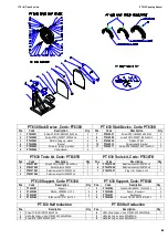
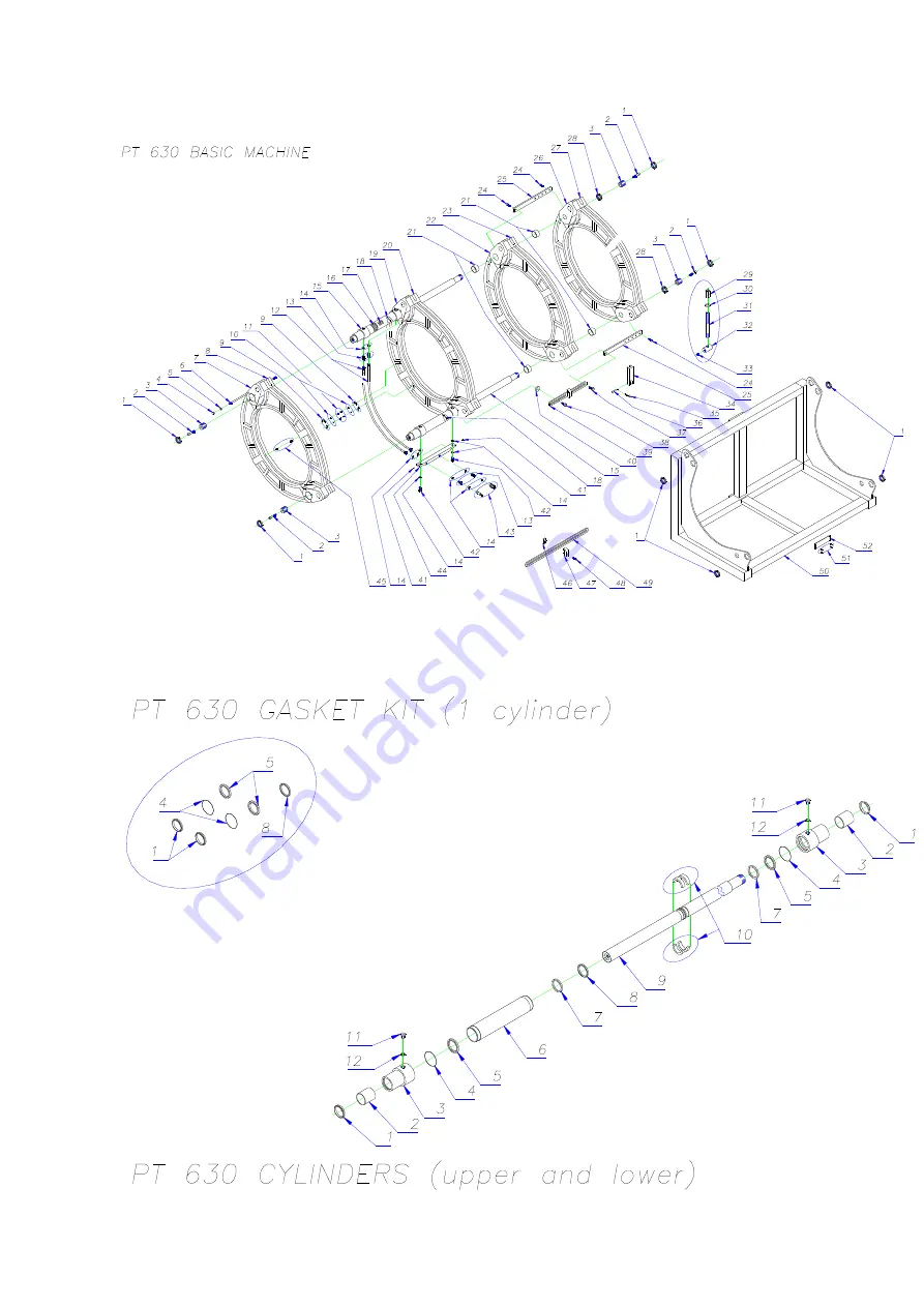
Page 27: ...I T S Ital Trade Services PT 630 Operating Manual 27 27 27 27 10 Exploded view and spare parts list ...

Page 28: ...630B42 Hollow screw 2 16 PT630B16 Technical data label 1 43 PT630B43 quick couplings M F 1 4 1 17 PT630B17 Serial no label 1 44 PT630B44 Oil colelctor 1 18 PT630B18 Danger label 2 45 PT630B45 Inserts pg n8x12 8 19 20 PT630B19 20 Second clamp 19 20 1 46 PT630B46 Block for heating mirror hook 1 21 PT630B21 50 30 FB1 bush 4 47 PT630B47 Mirror hook 1 22 23 PT630B22 23 Third clamp 22 23 1 48 PT630B48 S...

Page 29: ...I T S Ital Trade Services PT 630 Operating Manual 29 29 29 29 ...

Page 30: ... valve V03 M 1 67 PT630A67 Screw TCEI UNI 5931 8 8 6x16 zin 8 22 PT630A22 Handle 1 68 PT630A68 Engine flange c a HP 1 5 FLCA80 1 23 PT630A23 Distributor lever HD 104 L 185 1 69 PT630A69 Screw TCEI UNI 5931 8 8 6x20 zin 4 24 PT630A24 Complete distributor TC2 1 70 PT630A70 Joint gr 1 HP 1 5 1 25 PT630A25 Pressure regulating valve VEN 06 1 71 PT630A71 Pump joint g 1 x 0 27 reinf 1 26 PT630A26 Screw T...

Page 31: ...I T S Ital Trade Services PT 630 Operating Manual 31 31 31 31 ...

Page 32: ...upport for chain tightener shaft 1 16 PT630F16 Cable holder 3 53 PT630F53 O ring 119 NBR 2 62x15 08 616 1 17 PT630F17 Facing stopper screw 2 54 PT630F54 Nut DIN 981 30x1 5 1 18 PT630F18 Facing stopper 2 55 PT630F55 Washer 1 19 PT630F19 Hook 1 56 PT630F56 Screw TSPEI 5933 10 9 6x16 z 1 20 PT630F20 Plastic handle 2 57 PT630F57 Pinion x 3 16 Z 8 1 21 PT630F21 Screw TCEI UNI 5931 8 8 6x20 z 4 58 PT630...

Page 33: ...I T S Ital Trade Services PT 630 Operating Manual 33 33 33 33 ...

Page 34: ...2 5 16 PT630T16 Steatite terminal 4 mm2 4 52 PT630T52 Black flame retardant wire 1 5 mm2 5 17 PT630T17 Double red insul pipe 2x1mm2 P 8MM 4 53 PT630T53 Y G flame retardant wire 1 5 mm2 0 5 18 PT630T18 Blue insulating pipe 2 5 mm2 P 8MM 3 54 PT630T54 Plate for connecting box 1 19 PT630T19 Steatite terminal 16 mm2 4 55 PT630T55 Brass nut PG16 169 16 1 20 PT630T20 Brown insulating pipe 10mm2 P 12MM 2...

Page 35: ...8 8x45 zin 8 5 PT630TK05 Setscrew wrench UNI 6753 s 5 1 2 PT630TK02 Socket wrench 30X32 1 6 PT630TK06 Setscrew wrench UNI 6753 s 6 1 3 PT630TK03 Setscrew wrench UNI 6753 s 3 1 7 PT630TK07 Plug for hydraulic unit 1 4 PT630TK04 Setscrew wrench UNI 6753 s 4 1 PT 630 Support Code PT630U PT 630 Support Code PT630U Pos Code Description Qty Pos Code Description Qty 1 PT630U01 Support 1 5 PT630U05 Washer ...

Page 36: ...I T S Ital Trade Services PT 630 Operating Manual 36 36 36 36 This manual has been printed on December 2008 The technical data and information contained in this manual can be changed without any notice ...

Reviews: