_ TECNOEKA Srl _________________________________________________________ use and instruction manual _
_ page 14 ________________________________________________________________________________________
7. Instructions for use
COOK-TOP
-
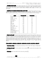
Cook-top control panel and use - On the control panel, 4 empty
and one fully coloured circles are placed next to each gas cock
knob of the cook-top (Fig. 6). The fully coloured one indicates the
position of the gas burner that is commanded by the knob in
question.
Fig. 6
-
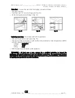
Electric lighting of the burners with safety device - The cook-top
is equipped with electric ignition of the burners by means of
spark plug “A” (Fig. 7). The spark plug operates when the push-
button on the control panel is pressed. This button is marked by
symbol
(spark). To ignite the burner press the electric ignition
push-button and, at the same time, press and turn in an
anticlockwise sense the knob of the burner that is to be started to
the symbol
(large flame/ignition spark). Release the electric
ignition push-button once the flame has appeared and keep the
gas cock knob pressed for about 6 - 8 sec., so as to let the safety
thermocouple “B” heat-up. Release the knob and turn it to the
position desired.
Fig. 7
Should the flame die-out, the safety thermocouple “B” will intervene automatically and close
the gas cock, thus blocking the gas flow to the respective burner.
To re-ignite the burner, turn the knob to the
•
(off) position and repeat the ignition
operations after having waited for approximately 1 minute. Each burner can operate at either
maximum or minimum level or at intermediate levels by setting the knob anywhere between
the maximum and minimum positions.
The various positions of the gas cock knob are indicated as follows:
-
position off
•
-
position for maximum
(large flame/ignition spark)
-
position for minimum
(small
flame)
Warning - The pots used on the cook-top burners should not have a concave or convex base
but rather, a full base (Fig. 8). They should have the following minimum diameter:
Mod. KCP96 V – KCP96 VS – KCP5 96 V – KCP5 96 VS
-
180 mm for the ‘semi-fast’ burner (front right burner);
-
220 mm for the ‘fast’ burner (back left-right burner; front left);
-
240 mm for the ‘triple crown’ burner (central burner).
Mod. KC 96 V – KC 96 VS – KC 96 M – KC 96 MS – KCR 96 V
-
180 mm for the ‘semi-fast’ burner (back right burner);
-
220 mm for the ‘fast’ burner (back left burner ; front left-right);
-
240 mm for the ‘triple crown’ burner (central burner).


