background image

_ TECNOEKA Srl __________________________________________________________ use and instruction manual _ 

_ page 8 _________________________________________________________________________________________ 

-


a single-pole switch with minimum between-contacts aperture of 3 mm, sized to the 
load and conforming to current legal regulations, is fitted between the appliance and the 
mains in the direct connection to the mains; 

-


the single-pole switch used for connection is easy to reach when the appliance is 
installed; 

-


the yellow/green earth wire is not interrupted by the switch; 

-


the power supply, when the appliance is operating, must not deviate from the rated 
voltage value by ±10%. 

-


make sure that after inserting the power supply cord into the terminal block it does not 
come into contact with any of the cooking range's hot parts. 

Connection to the water mains - The appliance must be fed with softened drinking water, 

with hardness from 0.5°F to 5°F (it is obligatory to use a softener to reduce the formation of 
lime inside the cooking chamber) and pressure in the range from 150 to 250 kPa (1.5 - 2.5 bar). 
Connection to the water mains should be made through the threaded 3/4" solenoid-valve on 
the rear of the appliance, fitting in between a mechanical filter and an on/off tap (before you 
connect the filter, allow a certain quantity of water to flow out in order to drain any waste from 
the pipe). 

Water drainage - One drainage tube comes out from the rear of the appliance, to drain the 

cooking compartment. You should connect one pipe to the drain tube, with an internal 
diameter of 30 mm (DN 30), resistant to vapour temperatures. To prevent choking, make sure 
that the pipe is stiff and that it does not have any elbows along the drainage path. Furthermore, 
the pipe must be at constant inclination (5% minimum) along its entire length (the length under 
consideration is from the drain tube of the appliance to the drainage point and must not exceed 
1 meter). The drainage pipe must lead to an open floor-level drain and, to ensure conformity to 
current legal regulations on hygiene, it must not come into direct contact with the drainage 
point. 

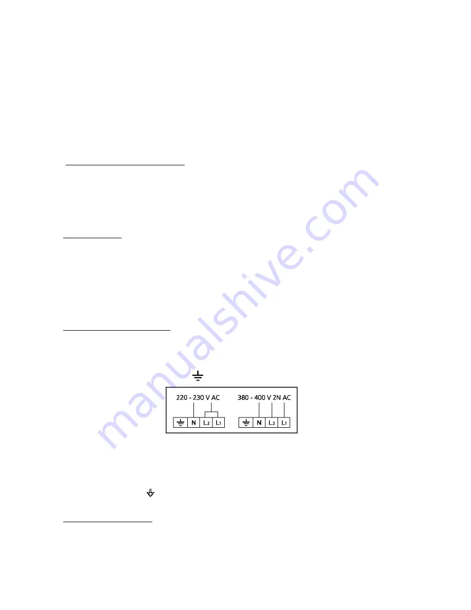
Connecting the power cable - To access the terminal board, just remove the appliance's left 

side-panel. Loosen the cable gripper and allow the cable to pass through it. Arrange the 
conductors so that the earth conductor is the last to detach from its terminal if the cable goes 
into a state of faulty traction. Connect the phase conductors to the terminals marked “L1” and 
“L2”, connecting the neutral conductor to the terminal marked "N" and the earth conductor to 
the terminal marked with the symbol 

 according to the following lay-out: 


(this electrical connection lay-out is located near the power supply terminal board ). Tighten the 
cable gripper and re-fit the left side-panel of the appliance. 
The appliance must be connected to an equipotential system whose efficiency must first be 
checked according to current legal regulations. 
This connection must be made between different appliances by using the appropriate terminal 
marked with the symbol  . The equipotential conductor must have a minimum diameter of 10 
mm

2

 The equipotential terminal is at the rear of the appliance. 

Safety thermal breaker - The appliance has a manually reset safety thermal breaker. It 

protects against excessive dangerous over-temperatures which could be accidentally generated 
inside the appliance. If the device is tripped, it interrupts electrical power to the appliance and 
thus prevents it from operating. To access this device, remove the left side-panel of the 
appliance. 

Summary of Contents for KF 981

Page 1: ...ND INSTRUCTION MANUAL MOD KF 981 KF 981 UD rev 0 TECNOEKA S r l Via I Nievo n 12 B 35012 Camposampiero Padova Italy Tel 39 049 9300344 39 049 5791479 Fax 049 5794387 www tecnoeka com E mail info tecnoeka com ...

Page 2: ...manual _ _ page 2 _________________________________________________________________________________________ Ekaserver Dati Sistema Gestione Qualità SGQ PRODOTTI Famiglia 1 FORNI FORNO ELETTRICO 40 60 90 LEka MANUALI D USO Forno Elettrico 40 60 90 LEka Manuale d uso KF 981 KF 981 UD GB rev 0 doc ...

Page 3: ...vo 12 B 35012 Camposampiero Pd Type of product Electric oven Model KF 981 KF 981 UD TECNOEKA Srl declares that the above mentioned products conform to the safety regulations under CEI EN 60335 1 Low voltage directive 2006 95 EC CEI EN 60335 2 42 CEI EN 55014 1 CEI EN 61000 3 2 Electromagnetic compatibility Directive 2004 108 EC CEI EN 61000 3 3 Machine Directive 98 37 EC Directive on the general s...

Page 4: ..._ TECNOEKA Srl __________________________________________________________ use and instruction manual _ _ page 4 _________________________________________________________________________________________ ...

Page 5: ..._____________________________ page 5 _ Index 1 Technical service 2 General warnings 3 Technical specifications 4 Instructions for the installer 5 Use instructions for the user 6 Residual risks for the user 7 How to use the control panel 8 Oven cooking 9 Cleaning 10 Maintenance 11 Technical service 12 Informations to the consumers 13 Wiring layout 14 The Warranty ...

Page 6: ... TO CONTROL THE GOODS specify the damage and get the driver to sign in acceptance send a claim in writing to the seller within 4 calendar days from the date of receipt No claim shall be accepted after such period The appliance is intended for professional use and must be utilised by qualified personnel trained to use it Any modification which may be necessary on the electrical system to enable ins...

Page 7: ...the parts in stainless steel Do not leave any glue residues on the surfaces If necessary remove them at once with an appropriate solvent Positioning Position the appliance perfectly horizontally on a table or similar support the table or support must be at least 85 cm above the floor Position it at a distance of not less than 10 cm from the side and rear walls to enable natural ventilating air to ...

Page 8: ...oes not have any elbows along the drainage path Furthermore the pipe must be at constant inclination 5 minimum along its entire length the length under consideration is from the drain tube of the appliance to the drainage point and must not exceed 1 meter The drainage pipe must lead to an open floor level drain and to ensure conformity to current legal regulations on hygiene it must not come into ...

Page 9: ...es are barriers which prevent the circulation of hot air Warm up the oven before every cooking operation to obtain maximum uniformity Do not salt foods in the cooking compartment 6 Residual risks for the user After a cooking operation open the door cautiously to avoid a violent outflow of heat which could cause burns While the oven is in operation pay attention to the hot zones marked on the appli...

Page 10: ... indicator light Fig 1 Fig 2 Fig 3 Programming cooking time To run the oven turn the programmer knob Fig 1 in line with symbol continuous operation or in line with the selected cooking time up to 120 minutes In the second case end of cooking is signalled by the oven switching OFF automatically Programming cooking temperature Turn the knob of the adjustment thermostat Fig 2 in line with the tempera...

Page 11: ...s operating and that cooking time is active Control thermostat indicator light The control thermostat orange indicator light goes OFF whenever the programmed temperature is reached inside the cooking compartment It lights up again when the thermostat is tripped to re establish this temperature Automatic humidifier indicator light The green indicator light of the automatic humidifier indicates that...

Page 12: ...roduct non toxic A common glass detergent can be used also to clean the glass panel of the door facing outward In all cases you may just use tepid soapy water After rinsing thoroughly dry the glass surface with a soft cloth If opaque sections form between the two glass panels of the door they can be eliminated after dismantling the internal glass panel Procedure unscrew the 4 screws securing the g...

Page 13: ...between the two door glasses to replace it remove the internal glass as described in the paragraph Cleaning the door After removing the internal glass replace the lamp with another with the same specifications 12V 35W 300 C this is a halogen lamp and should not be touched with your bare hands Changing the door seal The door seal has a rigid profile with 3 fixing tabs The profile must be fitted int...

Page 14: ...le prong loosened Contact a qualified technician to repair the prong One of the motors is blocked or turns slowly Contact a qualified technician to repair the motor The motors do not go into reverse Contact a qualified technician to repair the motor The oven does not cook evenly Heating element not powered or is damaged Contact a qualified technician to repair the element Damaged lamp Change the l...

Page 15: ...duce other equipment using recycled materials reducing the negative effects on the environment and public health which would be caused by incorrect management of the rubbish Should the user dispose of the product abusively administrative sanctions would be applied 13 Wiring layout WIRING LAYOUT MODD KF 981 KF 981 UD Key M Power terminal board IL Power line switch P End of cooking programmer T1 Saf...

Page 16: ...not compliant with the instructions given in the user s handbook supplied with the product 6 tampering with the product 7 adjustments and or maintenance and or repairs carried out by unauthorised personnel and or with non original spare parts 8 inadequate or careless maintenance of the product in contrast with the user s handbook supplied with the product 9 damages caused by fire natural disasters...

Reviews: