Overall accuracy: +/- 0,5 % fs
Sampling rate: 1 sample per second
Action: 1C type according to EN 60730-1
Compliance: ECC directive EMC 89/336 (EN 50081-1, EN 50082-1), ECC
directive LV 73/23 and 93/68 (EN 60730-1)
MEASUREMENT RANGE TABLE
-99.9 ... 700.0
- 999 ... 7000
4..20 mA, 0..20 mA,
0..10 V
(gener.)
---
0 ... +1600 °C
+32 ... +2912 °F
tc S (rh)
---
0 ... +1200 °C
+32 ... +2192 °F
tc K (Cr)
---
0 ... +800 °C
+32 ... 1472 °F
tc J (FE)
-50.0 ... +150.0 °C
-58.0 ... +302.0 °F
-50 ... +150 °C
-58 ... +302 °F
Ni 100 (ni)
-99.9 ... +600.0 °C
-99.9 ... +999.9 °F
-100 ... +600 °C
-148 ... +1112 °F
Pt 100 (Pt)
-50.0 ... +150.0 °C
-58.0 ... +302.0 °F
-50 ... +150 °C
-58 ... +302 °F
PTC
4 DIGIT with D.P.
4 DIGIT
PROBE
3 - INSTALLATION
MECHANICAL MOUNTING
:
The instrument, in DIN case 24 x 48 mm,
is designed for panel mounting. Make an hole 22 x 45 mm and insert the
instrument, fixing it with the provided special brackets .We recommend to
mount the gasket to obtain an IP 54 front protection. Avoid to place the
instrument in areas with humidity or dirt. Connect the instrument as far as
possible from source of electromagnetic disturbances so as motors, power
relays, relays, electrovalves,etc.
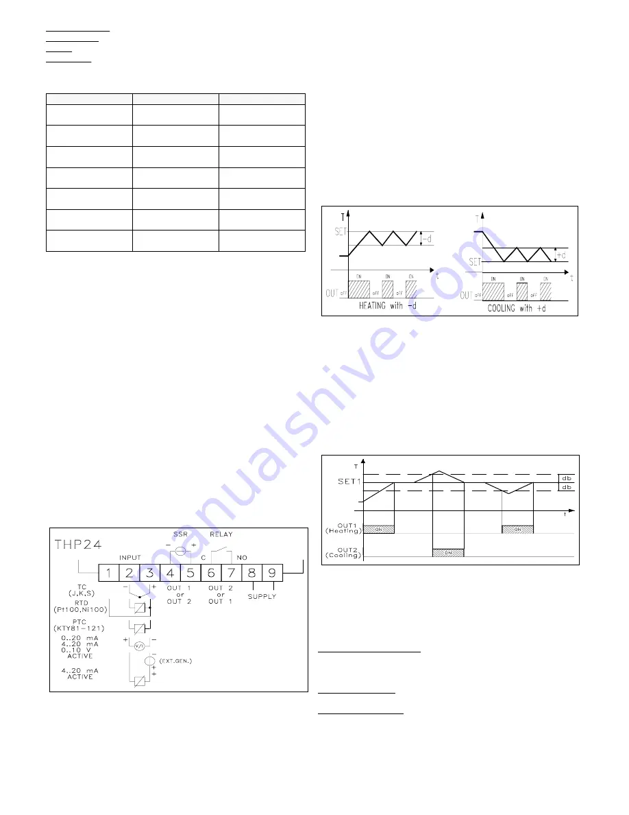
ELECTRICAL CONNECTIONS
: Carry out the electrical wiring
connecting only one wire for each terminal , according to the following
diagram, check that the power supply is the same as indicated on the
instrument and the loads current is not upper than the maximum current
admitted. The instrument, being a built in equipment with permanent
connection into a cabinet, is not furnished with internal device protecting
from overcurrent : it's recommended , therefore, to properly protect all the
electric circuits connected to the instrument, with devices (ex. fuses)
proportionate to the circulating currents. It's strongly recommended to use
cables with proper insulation, according to the working voltages and
temperatures. Furthermore, the input cable of the probe has to be kept
separate from line voltage wiring. If the input cable of the probe is
screened, it has to be connected on the ground with only one side. It is
advisable to check that the parameters are those desired before connecting
the outputs to the actuators so as to avoid malfunctioning . Whenever a
failure of the instrument could cause dangerous or damaging situations, it
should be kept in mind that the plant has to be provided with additional
devices to ensure the safety.
4 - OPERATING MODE
4.1 - ON/OFF CONTROL
The control mode of the instrument by ON/OFF mode occours on the
outputs according to the Sets point fixed, to the differential switching
points (par. "d1", "d2") and to operating modes (par. "HC1", "HC2")
programmed. For a correct functioning it is necessary to set a negative
differential switching point for reverse controls (ex.Heating processes) and
a positive differential switching point for direct controls (ex.Cooling
processes). Furtheremore the two Sets can be programmed independently
or dependently throught the parameter Sets Connection ("OCO"), and in
the case of set dependentlythe real regulation Set of output 2 will be
[Set1+Set2]. If output 2 is used as an alarm output, par. "OCO"
determines if the alarm is absolute or relative (in=absolute, di=relative)
and par. "HC2" determines if the alarm is low or high (H=low, C=high).
The operating mode can be also modified by means of outputs delay
parameter (par. "od") or Dynamic Set Point function, see the next
chapters for these functions.
4.2 - NEUTRAL ZONE CONTROL
The Neutral Zone control mode concerns both outputs and is generally
necessary for controllig a plant that possesses an Positive regulation
element (ex. Heating, Humidification etc.) and a Negative regulation
element (ex. Cooling, Dehumidification etc.) . The functioning is
determined by the Set1 (Set2 is automatically disconnected) and Neutral
Zone (par. "db"). Subsequently the regulator operates as follows: switches
off the outputs when the process value is the same as Set, switch on the
output OUT1 when the process value is under as [Set1-db], and switch on
the output OUT2 when the process value is upper as [Set1+db]. Thus the
Positive regulation element will be connected to output OUT1, while the
Negative regulation element is at output OUT2.
4.3 - PID CONTROL AND AUTOTUNING FUNCTION
PID control mode can only be carried out through output OUT 1 while
output OUT 2 can only operates by means of ON/OFF control mode with
Set 2 independent or dependended in respect with Set 1 and can therefore
be used as an alarm (see ON/OFF regulator). The PID algorithm of the
instrument is provided to program the following parameters:
For PROPORTIONAL term :
"Pb"
- Proportional Band,
"rst"
- Manual reset
"Ct"
- Cycle time.
For INTEGRAL term:
"It"
- Integral time
For DERIVATIVE term:
"dt"
- Derivative time
The instrument is set on parameters relative to PID control of standard
value. If ever these should result to be unsuitable it would be advisable to
TECNOLOGIC - THP 24
USER MANUAL (I - GB) - Vr. 01 - ISTR 00239 - PAG. 6


