background image

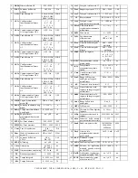
30

0 ÷ 9999 sec.

Tempo derivativo

dEr

33

500

0 ÷ 9999 sec.

Tempo integrale

Int

32

100

1 ÷ 9999

Banda proporzionale

Pb

31

SP

SP / Load

Ottimizzazione autotuning

PidP

30

no

no / FaSt

SP / LoSP

Autotuning

Auto

29

no

no / yES

Selftuning

SELF

28

AL4

AL4 /

Pid / 3Pt

Funzione dell'uscita
C2/A4

C2

27

HEat

HEat / CooL

Modo di funzionamento
uscita C1

Func 

26

Pid

Pid /

OnFS / OnFa

Tipo di regolazione

Cont

25

9.999

SPLL ÷ 9999

Set Point massimo

SPHL

24

-999

-999 ÷ 9999

Set Point minimo

SPLL

23

no

no / yES

Soglie allarmi
programmabili nel menù
"ConF"

ALPr

22

0

0 ÷ 9999 sec.

Tempo massimo allarme
Loop Break

LbAt

21

0

0 ÷ 100 %

Potenza per allarme Loop
Break

LbAP

20

OPEn

OPEn / CLoS

Logica di attivazione
uscita HB

rLHb

19

OFF

OFF / On

Comportamento allarme
A4 in regolazione OFF

AL4o

18

- - C

- - C / - - o

 - SC / - So

 L - C / L - o

LSC / LSo

Configurazione
funzionamento allarme
A4

AL4c

17

LOAb

LOAb / HIAb

LHAb / LOdE

HIdE / LHdE

Tipo allarme A4

AL4t

16

OFF

OFF / On

Comportamento allarme
A3 in regolazione OFF

AL3o

15

- - C

- - C / - - o

 - SC / - So

 L - C / L - o

LSC / LSo

Configurazione
funzionamento allarme
A3

AL3c

14

LOAb

LOAb / HIAb

LHAb / LOdE

HIdE / LHdE

Tipo allarme A3

AL3t

13

OFF

OFF / On

Comportamento allarme
A2 in regolazione OFF

AL2o

12

- - C

- - C / - - o

 - SC / - So

 L - C / L - o

LSC / LSo

Configurazione
funzionamento allarme
A2

AL2c

11

LOAb

LOAb / HIAb

LHAb / LOdE

HIdE / LHdE

Tipo allarme A2

AL2t

10

OFF

OFF /  On

Comportamento allarme
A1 in regolazione OFF

AL1o

9

- - C

- - C / - - o

 - SC / - So

 L - C / L - o

LSC / LSo

Configurazione
funzionamento allarme
A1

AL1c

8

LOAb

LOAb / HIAb

LHAb / LOdE

HIdE / LHdE

Tipo allarme A1

AL1t

7

Hb

AL3, Hb

Funzione dell'uscita
A3/HB

FAL3

6

1

-999 ÷ 9999

Isteresi allarme A4

HAL4

5

no

no / yES

Cambiamento Set point
attivo con tasto UP

SPOL

63

no

no / yES

Abilitazione regolazione
manuale nel menù "SEL"

EnOL

62

0

-99.9 ÷100.0 %

Potenza di regolazione
manuale quando attivata
da AUXIN

rEdF

61

FF

FF /Fr /rF /rr

Funzione ingressi AUXIN

rEAr

60

1

 1 ÷ 4

Numero Set point
programmabili

nSP

59

LoCL

LoCL / LorE

Accesso alla
programmazione tramite
porta seriale

PacS

58

4800

300/600/1200/

2400/4800/

9600 baud

Baud rate porta seriale

baud

57

1

1 ÷ 255

Indirizzo della stazione
per comunicazione seriale

nSta

56

50H

50H / 60H Hz

Frequenza reiezione del
rumore

FrEq

55

1

0 ÷ 50 sec.

Costante del filtro digitale
ingresso

Filt

54

0

-999 ÷ 9999

Calibrazione

OFFt

53

0

0 / no_0

Range delle uscite
analogiche

Aout

52

0

-999 ÷ 9999

Limite superiore scala
ingresso analogico segnali
normalizzati

EndS

51

0

-999 ÷ 9999

Limite inferiore scala
ingresso analogico segnali
normalizzati

StrS

50

0

 0 ÷ 3

Numero di cifre decimali

 dP

49

SSLo

SSLo / SSHi

Range dell'ingresso
analogico per segnali
normalizzati

ScaL

48

C

C / F / r

Unità di misura della
temperatura

Unit

47

0

-99.9 ÷ 999.9

°C/°F/°R

Temperatura
compensazione giunto
freddo

tCJC

46

no

no / YES

Compensazione esterna
giunto freddo

ECJC

45

J

b / E / J / CrAl

/ n / r / S / t / L

/ u / Pt1 / Pt2 /

0_50

Sonda in ingresso

SEnS

44

0

0.00 ÷ 99.99

unit/min.

Velocità della rampa di
discesa

SloF

43

0

0.00 ÷ 99.99

unit/min.

Velocità della rampa di
salita

Slor

42

no

no / 

OPEn / CloS

Posizionamento
all'accensione
azionamento motorizzato

PoSi

41

0

0  ÷  9999

Zona morta

dbEr

40

0

0 ÷ 10 %

Valore minimo di
regolazione azionamento
motorizzato

SHrI

39

4

4 ÷ 1000 sec.

Tempo di corsa
azionamento motorizzato

  tcor  

38

50.0

-99.9÷100.0 %

Reset manuale

rS

37

30

1 ÷ 255 sec.

Tempo di ciclo uscita  C2

tcr2

36

1.00

0.00 ÷ 99.99

Rapporto potenza C2 / C1

Prat

35

30

1 ÷ 255 sec.

Tempo di ciclo uscita C1

tcr1

34

TECNOLOGIC - THP 94


 USER MANUAL (I - GB) - Vr. 05   - ISTR 01195  - PAG. 11

Summary of Contents for THP 94

Page 1: ...ELLE USCITE DI ALLARME 4 11 RAGGIUNGIMENTO DEL SET POINT A VELOCITA CONTROLLATA 4 10 USCITE DI REGOLAZIONE ANALOGICHE 4 9 FUNZIONI DI AUTOTUNING E SELFTUNING 4 8 REGOLATORE PID PER AZIONAMENTI MOTORIZZATI 4 7 REGOLATORE PID A DOPPIA AZIONE 4 6 REGOLATORE PID A SINGOLA AZIONE 4 5 REGOLATORE ON OFF 4 4 CONFIGURAZIONE INGRESSO DI MISURA 4 3 SELEZIONE DEL SET POINT ATTIVO 4 2 STATI DI REGOLAZIONE 4 1 ...

Page 2: ...l valore di processo 12 Display SV Indica normalmente il valore di Set Point 1 2 CODIFICA DELLO STRUMENTO THP 94 a b c d e f g h i l a INGRESSO T Per sonde di temperatura Termocoppie Termoresistenze Pt100 o segnali in mV 0 50 mV I Segnali normalizzati 0 4 20 mA V Segnali normalizzati 0 1 5 V W Segnali normalizzati 0 2 10 V b USCITA C1 R A relè e in tensione 24 VDC per SSR C Analogica 0 4 20 mA V A...

Page 3: ...ZIONE MONTAGGIO MECCANICO Lo strumento in contenitore DIN 48 x 96 mm è concepito per il montaggio ad incasso a pannello Praticare quindi un foro 45 x 92 mm ed inserirvi lo strumento fissandolo con le apposite staffe fornite Si raccomanda di montare l apposita guarnizione per ottenere il grado di protezione frontale IP54 Evitare di collocare la parte interna dello strumento in luoghi soggetti ad al...

Page 4: ...rio impostare al parametro tCJC la temperatura alla quale si trova il giunto freddo Nel caso venga scelto l ingresso 0 50 mV è necessario impostare al parametro StrS il valore che lo strumento deve visualizzare a 0 mV e al parametro EndS il valore che lo strumento deve visualizzare a 50 mV Per quanto riguarda gli strumenti con ingresso per segnali analogici normalizzati è invece necessario imposta...

Page 5: ...iclo di sintonizzazione terminato il quale i parametri vengono memorizzati dallo strumento e durante la regolazione rimangono costanti La funzione di SELFTUNING self tuning rule based IN TUNE prevede invece il monitoraggio della regolazione e il continuo ricalcolo dei parametri durante la regolazione Per attivare la funzione di AUTOTUNING procedere come segue 1 Impostare ed attivare il Set point d...

Page 6: ...a della rampa in salita Valore di processo minore del Set point espressa in unità minuto SloF Pendenza della rampa in discesa Valore di processo maggiore del Set point espressa in unità minuto Quando si cambia il valore del Set point o alla sua accensione lo strumento determina automaticamente quale dei due valori utilizzare La funzione risulta disattivata quando si impostano i parametri a 0 4 11 ...

Page 7: ...lore impostato al parametro ALHb Al parametro ALHb andrà quindi impostato il valore della corrente normalmente assorbita dal carico comandato dall uscita C1 tenendo conto anche delle fluttuazioni della tensione di rete per evitare allarmi indesiderati Per quanto riguarda l isteresi dell allarme HB essa viene calcolata automaticamente dallo strumento come il 2 di ALHb ed il comportamento è analogo ...

Page 8: ...mendo il tasto P e mantenendolo premuto per circa 3 sec si accede al menù di selezione SEL Mediante il tasto UP è possibile quindi scorrere le selezioni rEG permette di porre il regolatore in stato di regolazione automatica OPEr permette di accedere al menù dei parametri operativi ConF permette di accedere al menù dei parametri di configurazione SPn permette di selezionare il Set point attivo e co...

Page 9: ...bili i parametri relativi alle soglie degli allarmi nel menù OPEr no o nel menù ConF yES SPLL SET POINT MINIMO Valore minimo impostabile come Set Point o limite inferiore dei Set Point SPHL SET POINT MASSIMO Valore massimo impostabile come Set Point o limite superiore dei Set Point Cont TIPO DI REGOLAZIONE Permette di selezionare uno dei possibili modi di regolazione che lo strumento offre ON OFF ...

Page 10: ... strumento nella rete di comunicazione Impostare quindi un numero diverso per ogni stazione da 1 a 255 baud BAUD RATE PORTA SERIALE Impostare la velocità di trasmissione dei dati Baud rate della rete in cui è inserito lo strumento Tutte le stazioni devono avere la stessa velocità di trasmissione PacS ACCESSO ALLA PROGRAMMAZIONE TRAMITE PORTA SERIALE Se impostato come LoCL significa che lo strument...

Page 11: ...point attivo con tasto UP SPOL 63 no no yES Abilitazione regolazione manuale nel menù SEL EnOL 62 0 99 9 100 0 Potenza di regolazione manuale quando attivata da AUXIN rEdF 61 FF FF Fr rF rr Funzione ingressi AUXIN rEAr 60 1 1 4 Numero Set point programmabili nSP 59 LoCL LoCL LorE Accesso alla programmazione tramite porta seriale PacS 58 4800 300 600 1200 2400 4800 9600 baud Baud rate porta seriale...

Page 12: ...olid state relays SSR or analogue signals and till 4 alarms outputs A1 2 3 4 all of them relay or to drive solid state relays SSR The input accepts temperature probes Thermocouple PT100 thermoresistances or mV signals or normalised analogue signals 0 1 5V 0 2 10V 0 4 20 mA Furthermore the instrument is available with a current transformer input for the Heater Break function and with 2 auxiliary di...

Page 13: ...99 9 9 99 99 99 0 999 9 999 999 9999 0 50 mV 0_50 0 4 20 mA 0 1 5 V 0 2 10 V gener 99 9 630 0 C 99 9 999 9 F 99 9 504 0 R 200 630 C 328 1166 F 160 504 R Pt100 JIS Pt2 99 9 850 0 C 99 9 999 9 F 99 9 680 0 R 200 850 C 328 1562 F 160 680 R RTD Pt100 IEC Pt1 99 9 600 0 C 99 9 999 9 F 99 9 480 0 R 200 600 C 328 1112 F 160 480 R tc U u 99 9 900 0 C 99 9 999 9 F 99 9 720 0 R 150 900 C 238 1652 F 120 720 ...

Page 14: ...trolling Set point and then to select which one has to be active The maximum Set point number is determined by the par nSP in SEL menu The Set point to be activated can be selected From the keyboard through parameter SPn in SEL menu From the keyboard through Up key if par SPOL yES Through the digital auxiliary inputs AUXIN if the input function par rEar allows it When nSP 1 par SPn doesn t appear ...

Page 15: ...safety contacts that stop the action at travel end it s necessary to equip the plant with these stroke end SQo SQc as shown in picture below The PID control mode for motorized actuactors works on C1 and C2 outputs depending on the set point SEt1 and on the programmed control algorithm which foreseen the programming of the following parameters For PROPORTIONAL term Pb Proportional Band rS Manual re...

Page 16: ...Auto and PidP are not appearing anymore To stop the Autotuning cycle or to deactivate the Selftuning select from SEL menu any of the control state reG OPLO or OFF If the instrument is switched off during Autotuning or Selftuning at its switching on it will begin again the cycle 4 9 ANALOGUE CONTROL OUTPUTS C1 C2 In case that the control outputs C1 and or C2 are current or tension type it occurs to...

Page 17: ...f it to be used as Heater Break function par FAL3 HB Furthermore it s usable only when C1 output is digital type or Relay or SSR If A3 HB is present the instrument will have an input TAHB able to measure the load current driven by C1 output This kind of input accepts signals coming from current transformers TA till a maximum of 200 mA at 200 mA the instrument measure a value of 100 0 Therefore to ...

Page 18: ...nals it s advisable to adopt a screened cable wired as in the drawing Adopting this electrical drawing and having care that the total capacity of the line would not be higher than 200 nF the total length of the line can reach a maximum of 1500 meters If the instrument is equipped with the serial interface the parameters to be programmed are the following nStA Address of the station Set a different...

Page 19: ...referred to A4 alarm AL3c CONFIGURATION OF A4 ALARM FUNCTIONING MODE Equal to AL1c but referred to A4 alarm AL4o A4 ALARM BEHAVIOUR IN OFF CONTROL MODE Equal to AL1o but referred to A4 alarm rLHb OUTPUT HB LOGIC MODE Permits to establish the Heater Break alarm A3 HB functioning mode setting the output rest state nO normally deactivated nC normally activated LbAP LOOP BREAK ALARM POWER Value of C1 ...

Page 20: ...IGITAL FILTER CONSTANT Time constant of the software filter referred to the input value measurement expressed in seconds FrEq FREQUENCY OPTIMISING THE NOISE The instrument is equipped with filter to limit the input noises originated by the net To optimise the functioning set then on this par the net frequency on which it s connected the instrument 50 Hz 50H or 60 Hz 60H nStA ADDRESS OF THE STATION...

Page 21: ...ive Set point change using UP key SPOL 63 no no yES Manual contron activation in SEL menu EnOL 62 0 99 9 100 0 Manual control power when activated by AUXIN rEdF 61 FF FF Fr rF rr AUXIN input function rEAr 60 1 1 4 Programmable Set point number nSP 59 LoCL LoCL LorE Programming access through serial port PacS 58 4800 300 600 1200 2400 4800 9600 baud Baud rate serial port baud 57 1 1 255 Address of ...

Page 22: ...de active the regulation These referred to a bad functioning of the input sensor will switch the instrument into OFF condition HOW TO CLEAN We recommend to avoid abrasive cleaners or containing solvents which could damage the instrument WARRANTY AND REPAIRS The instrument is under warranty against construction vices or defected material noticed within 12 months from delivery date The warranty is l...

Reviews: