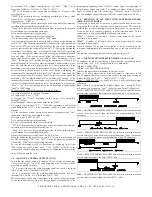
not activated if PV is higher than [SetPoint / 2] ("Func"="HEAT") or is
lower than [Se SetPoint / 2] ("Func"="Cool").
-"SP" if it's desired to have Autotuning oscillating on Set point value
programmed, or:
-"LoSP" if it's desired to have the Autotuning oscillating on a lower value
(equal to 70% of Set point programmed)
8) program par. "PidP" as :
-"SP" if it's desired to have Autotuning in order to optimise the parameter
calculation for eventual Set point variations, or :
-"Load" if it's desired to have Autotuning in order to optimise the parame-
ter calculation for eventual load variations
9) Go out from parameters programming
10) Connect the instrument to the plant controlled
11) Start Autotuning selecting "tunE" in "SEL" menu
Now, the Autotuning function is activated and it's shown by the flashing of
the led "AT". The regulator automatically tunes all the right parameters
for a correct PID control mode. Wait then for the end of the Autotuning
process, indicated by the switch off of the led "AT". During the Autotuning
execution of oscillatory type, are activated some ON-OFF regulation
cycles, that consequently make temperature swinging abundantly around
set point value. If the process doesn't allow big temperature variations
upper than Set point value, it's advisable to select Autotuning cycle as
"LoSP". In this case the SV display, during the Autotuning, will show a Set
point value equal to 70% of Set point programmed. The Autotuning proce-
dure has been limited at a maximum time of 12 hours, afterwards, if the
Autotuning is not completed the instrument will show on the display "toAt".
In case, instead, should occurs a probe error during Autotuning, the
instrument will automatically switch into "OFF" state and, at the end of the
error, the instrument will visualise "noAt". In this case active again the
Autotuning. The calculated values will be automatically storage by the
instrument at the end of the Autotuning cycle, into the PID control parame-
ters. Once terminated the Autotuning cycle, do remember to program par.
"Auto" = "no" if it's not desired to see the Autotuning activation option
"tunE" in "SEL" menu.
To enable the SELFTUNING function proceed as follows :
1) Program and active the desired "Set point".
2) Program par. "Cont" = "Pid".
3) Program par. "Func" depending on the process to be controlled,
through C1 output.
If the instrument control a motorised actuator set "HEAt".
4) Program, if present, par. "C2" = "-Pid" if the instrument control a plant
with double action or "3Pt" if the instrument control a 3 point motorised
actuator.
5) If the instrument control a motorised actuator, program on par. "tcor"
the actuator travel time, expressed in seconds.
6) Program par. "SELF" as "yES".
7) Go out from parameters programming
8) Connect the instrument to the plant controlled
-"SP" if it's desired to have Autotuning in order to optimise the parameter
calculation for eventual Set point variations, or :
-"Load" if it's desired to have Autotuning in order to optimise the parame-
ter calculation for eventual load variations
9) Start the Selftuning selecting "tunE" on "SEL" menu
When the Selftuning function is active, led "AT" is fixly switched on and all
the PID parameters ("Pb", "Int", "dEr", etc.) and Autotuning parameters
("Auto" and "PidP") are not appearing anymore.
To stop the Autotuning cycle or to deactivate the Selftuning, select from
"SEL" menu any of the control state : "reG", "OPLO" or "OFF". If the
instrument is switched off during Autotuning, or Selftuning, at its switching
on it will begin again the cycle.
4.9 - ANALOGUE CONTROL OUTPUTS (C1,C2)
In case that the control outputs (C1 and/or C2) are current or tension type
it occurs to set on par. "Aout" the scale beginning used. Therefore, will be
programmed on this parameter :
- "0" if it's desired to use the scale beginning equal to 0 (0 mA if the input
is 0/4...20 mA, or 0V if the input is 0/2...10V)
- "no 0" if it's desired to use the scale beginning different from 0 (4 mA if
the input is 0/4...20 mA, or 2 V if the input is 0/2...10V).
The output signal will be then proportional to the control power calculated
by the instrument starting from 0% (output signal corresponding to the
programmed beginning scale) till 100% (output signal corresponding to
the maximum output end scale).
The analogue outputs are used just in
single or double action PID control type. When the control is ON/OFF
type, the analogue output can assume only the control state 0% or 100%.
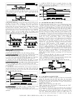
4.10 - REACHING OF SET POINT WITH CONTROLLED SPEED
(RISE AND FALL RAMPS)
It's possible to reach the set point in a predetermined time (in any case
longer than the time that the plant would naturally need) This could be
useful in that processes (heating or chemical treatments, etc.) on which the
set point has to be reached gradually, in predetermined times. To this
propose have to be programmed the following parameters :
"Slor"
- Gradient of rise ramp (Process value minor of Set point)
expressed in unity/minut.
"SloF"
- Gradient of fall ramp (Process value higher than Set point)
expressed in unity/minut.
When is changed the set point value (SEtn) or at the switching on, the
instrument automatically determines which one of the two values has to
use.
The function results deactivated when the parameters are = 0.
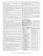
4.11 - ALARM OUTPUTS OPERATING MODE (A1,A2, A3, A4)
To configure the alarms functioning, whom activation is depending on the
process value (A1,2, 3, 4 ), it's necessary to set 2 parameters :
"ALnt"
-
ALARM TYPE
"ALnc"
- ALARM CONFIGURATION
(where n indicates the alarm number to which we refer)
Note
: A3 and A4 alarms can be used as alternative, respectively to HB
and C2 outputs. Therefore it's necessary to chose the output functioning as
alarms through par. "FAL3" = "AL3" and "C2" = "AL4".
"ALnt"
-
ALARM TYPE
:
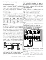
It's possible to have 6 different alarm output
behaviours.
Note
: When it's programmed the window alarm type , instead of "ALn"
will appear two parameters "ALnL" (Lower set) and "ALnH" (Higher set).
LOAb = ABSOLUTE MINIMUM ALARM
:
The alarm is activated when the
process value goes under the alarm set programmed on "ALn" parameter.
HIAb = ABSOLUTE MAXIMUM ALARM: The alarm is activated when the
process value goes upper than the alarm set programmed on "ALn"
parameter.
LHAb = ABSOLUTE WINDOW ALARM: The alarm is activated when the
process value goes under the alarm set programmed on "ALnL" parameter
or goes upper than the alarm set programmed on "ALnH" parameter.
LOdE = RELATIVE MINIMUM ALARM: The alarm is activated when the
process value goes under the value [SEtP - ALn ].
HIdE = RELATIVE MAXIMUM ALARM: The alarm is activated when the
process value goes upper than the value [SEtP + ALn ].
TECNOLOGIC - THP 94
USER MANUAL (I - GB) - Vr. 05 - ISTR 01195 - PAG. 16

