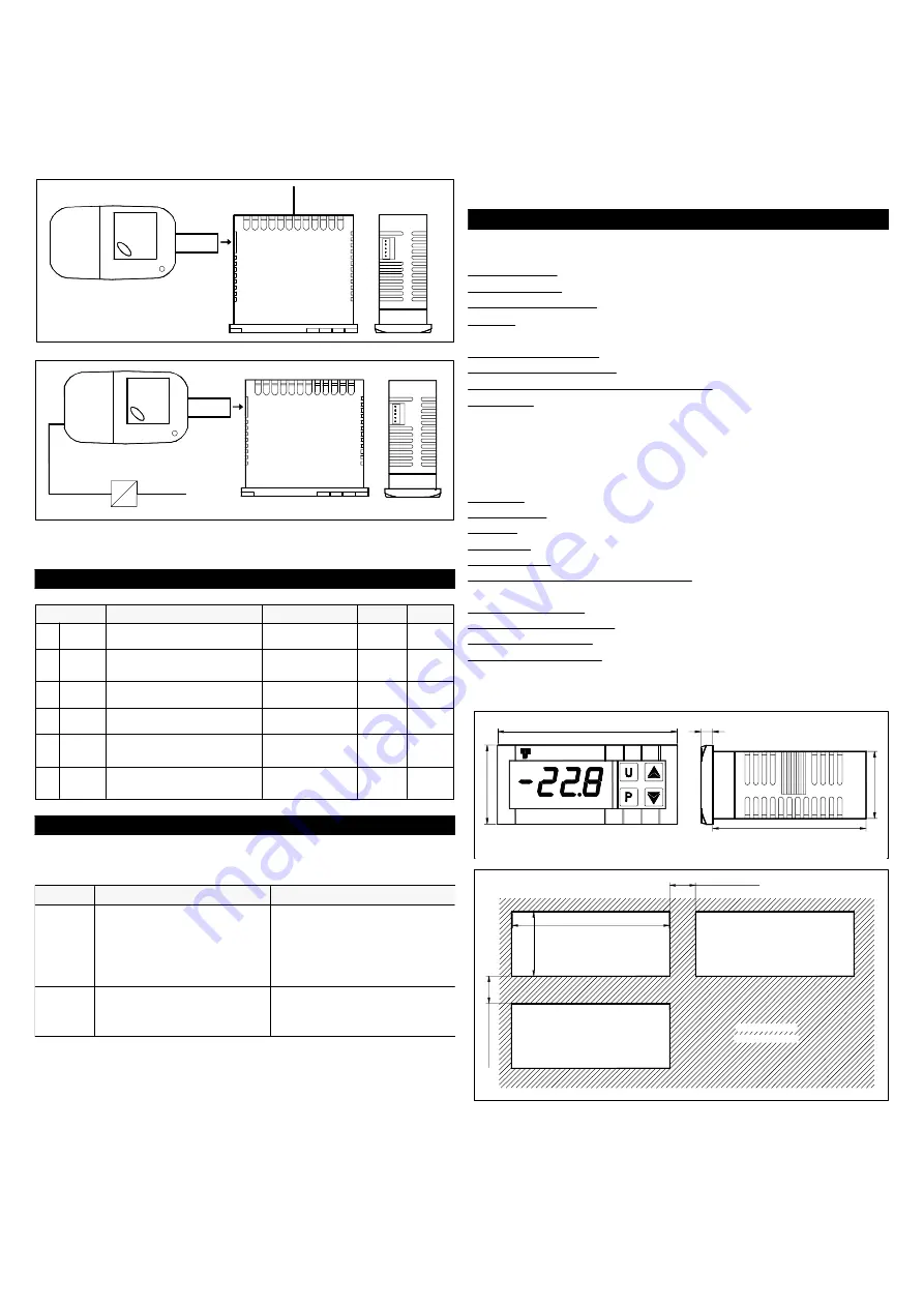
parameters through the device
TECNOLOGIC KEY01
with
5 poles
connector.
This device it’s mainly useable for the serial programming of the
instruments which need to have the same parameters configuration
or to keep a copy of the programming of an instrument and allow its
rapid retransmission.
To use the device KEY01 it’s necessary that the device or
instrument are being supplied.
Instrument supplied and device not supplied
SUPPLY
Instrument supplied from the device
SUPPLY ADAPTER
12 VDC
AC SUPPLY
For additional info, please have a look at the KEY01 instruction
manual.
5 - PROGRAMMABLE PARAMETERS TABLE
OFF
OFF ÷ 9999
Access Password to
parameter functions
PASS
6
2.0
OFF ÷ 20.0
sec
Measurement filter
FiL
5
On
On - OFF
Decimal point
dP
4
°C
°C - °F
Unit of measurement
Unit
3
0.0
-30.0 ÷ 30.0
°C/°F
Probe Calibration
OFS
2
ntc
Ptc - ntc
Probe Type
SEnS
1
Note
Def.
Range
Description
Par.
6 - PROBLEMS, MAINTENANCE AND GUARANTEE
6.1 - SIGNALLING
Error Signalling:
Check and if necessary
re-programme the
parameters function.
Internal memory error
EEPr
Check the correct
connection of the probe
with the instrument and
check the probe works
correctly
The probe may be
interrupted or in short
circuit, or may measure
a value outside the
range allowed
E1
-E1
Action
Reason
Error
6.2 - CLEANING
We recommend cleaning of the instrument with a slightly wet cloth
using water and not abrasive cleaners or solvents which may
damage the instrument.
6.3 - GUARANTEE AND REPAIRS
The instrument is under warranty against manufacturing flaws or
faulty material, that are found within 12 months from delivery date.
The guarantee is limited to repairs or to the replacement of the
instrument.
The eventual opening of the housing, the violation of the instrument
or the improper use and installation of the product will bring about
the immediate withdrawal of the warranty’s effects.
In the event of a faulty instrument, either within the period of
warranty, or further to its expiry, please contact our sales
department to obtain authorisation for sending the instrument to
our company.
The faulty product must be shipped to TECNOLOGIC with a
detailed description of the faults found, without any fees or charge
for Tecnologic, except in the event of alternative agreements.
7 - TECHNICAL DATA
7.1 - ELECTRICAL DATA
Power supply: 12 VAC/VDC, 24 VAC/VDC, 100..240 VAC +/- 10%
Frequency AC: 50/60 Hz
Power consumption: 3 VA approx.
Input/s: 1 input for temperature probes: PTC (KTY 81-121, 990
Ω
@ 25 °C) or NTC (103AT-2, 10K
Ω
@ 25 °C)
Installation category: II
Measurement category: I
Protection class against electric shock: Class II for Front panel
Insulation:
Reinforced insulation between the low voltage part
(supply) and front panel; Reinforced insulation between the low
voltage section (supply) and the extra low voltage section (input);
No insulation between supply F type and input.
7.2 - MECHANICAL DATA
Housing: Self-extinguishing plastic, UL 94 V0
Dimensions: 33 x 75 mm, depth 64 mm
Weight: 100 g approx.
Mounting: Flush in panel in 29 x 71 mm hole
Connections: 2,5 mm
2
screw terminals block
Degree of front panel protection : IP 65 mounted in panel with
gasket
Pollution situation: 2
Operating temperature: 0 ... 50 °C
Operating humidity: 30 ... 95 RH% without condensation
Storage temperature: -10 ... +60 °C
7.3 - MECHANICAL DIMENSIONS, PANEL CUT-OUT AND
MOUNTING [mm]
75
33
5
64
28
TLV 10
RECOMMENDED
PANEL CUTOUT
29
71
min. 15 mm
mi
n. 12
mm
TECNOLOGIC - TLV 10
- OPERATING INSTRUCTIONS - Vr.01 - 11/05 - ISTR 06939 - PAG. 3


