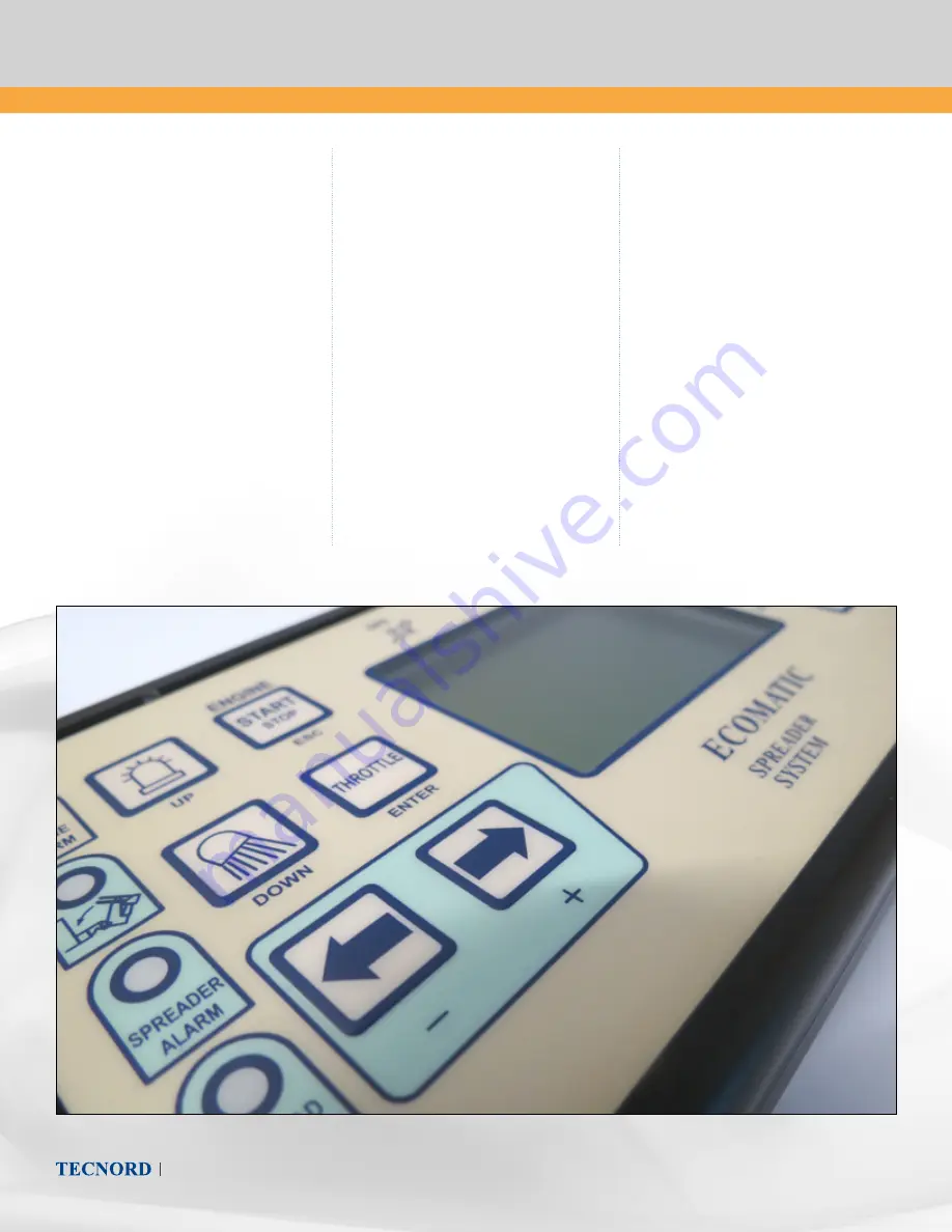
background image

PAGE 4

User Manual 

- Ecomatic 2010

3.

 System Use

POWER SUPPLY

The power supply can be 12Vdc direct current 

or 24Vdc direct current (depending upon the 

application and the relay kit ordered with the 

system).

Always supply power to the system with the 

correct voltage in order to avoid breakdowns 

and system failures.

After system installation, connect it to the 

battery. Connect the blue wire to the positive 

terminal and the brown wire to the negative 

terminal.

Even though the system is protected against 

reverse polarity of the power supply, always 

be careful to perform the correct cable 

connection.

To activate the system, release the emergency 

push-button.

Press the emergency push-button whenever 

needed.

Before disconnecting the control unit, press 

the main push-button or the emergency 

push-button to make sure the

system isn’t powered.

SYSTEM START

The system is started by the switch button 

#1 which will activate the system by the 

main relay contained in the shunt box. If the 

emergency push-button is not released, the 

system will not start.

If the system has been successfully started, 

the display will turn on.

ENGINE START/STOP

With the engine turned off and the oil 

pressure warning light turned on, (warning 

light #3), the engine can be started by 

holding the Engine Start (pushbutton #5) for 

at least three seconds.

The three seconds are those needed by the 

diesel engine glow plugs.

If the engine is running, pushing again the 

pushbutton #5 will activate the engine stop.

If the engine is running, the light #3 indicates 

the amount of fuel reserve.

Summary of Contents for Ecomatic 2010

Page 1: ...tal inputs for engine control alternator accelerator oil alarm 1 digital input for tachometer squared sinusoidal half wave signals Other 2 analog inputs Other 3 digital inputs Note almost all inputs are analog and can be configured as digital PNP or NPN 12 OUTPUTS 3 PWM current outputs with feedback 1500mA max 3A as option 5 outputs for engine management alternator accelerator decelerator start st...

Page 2: ...UMINATED PUSHBUTTON 2 FUNCTION UP It works as a set reset pushbutton Switches on and off the rotating lamps In the diagnostic or calibration mode it is the UP pushbutton menu scroll up 5 ENGINE ON OFF ILLUMINATED PUSHBUTTON 2 FUNCTION ESC When the engine is off the pushbutton activates the engine start in presence of an oil pressure alarm signal When the engine is running the starter will not be a...

Page 3: ...o a maximum by acting on the proportional valve which controls the spinner engine 14 MENU ILLUMINATED PUSHBUTTON Illuminated pushbutton which allows to enter the diagnostic or calibration mode menu 15 BACKLIT DISPLAY It shows the current operating modes and parameters 16 ILLUMINATED PUSHBUTTON FOR RIGHT TAIL SHIFTING 2 FUNCTION Operate the DC motor for right tail shifting In the diagnostic or cali...

Page 4: ...ency push button whenever needed Before disconnecting the control unit press the main push button or the emergency push button to make sure the system isn t powered SYSTEM START The system is started by the switch button 1 which will activate the system by the main relay contained in the shunt box If the emergency push button is not released the system will not start If the system has been success...

Page 5: ...he operating mode has been selected it is validated by holding the pushbutton 14 It is possible to choose between the following operating modes MIX SALT 1 moistened salt spreading with the 1st parameter set MIX SAND 1 moistened sand or gravel spreading with the 1st parameter set MIX SALT 2 moistened salt spreading with the 2nd parameter set MIX SAND 2 moistened sand or gravel spreading with the 2n...

Page 6: ...hift actuator with potentiometer D SPREADING WIDTH IN METERS Value settable with potentiometer 13 between 1 and 12 meters E LIQUID PERCENTAGE OF THE TOTAL AMOUNT OF MATERIAL IN Value settable between 0 and 30 with the potentiometer 11 Should the liquid be low the percentage value is replaced by and the Spread Alarm 19 will blink F MATERIAL AMOUNT SELECTED FOR SPREADING IN g m Value settable betwee...

Page 7: ... the spreading mode e g when the vehicle stops at a stop light Spreading mode activates only if the spinner is not raised or when the warning light 20 is turned off When this warning light is on the spreading is stopped and the relative Spread On warning light 18 is turned off In order to resume spreading the spinner must be lowered to its normal operating position and the spreading activation pus...

Page 8: ... Conveyor EV Water pump EV Spinner EV Current values in mA PUSHBUTTONS Control box push buttons Push button position released pushed on the control box 0 Released 1 Pushed SIMMETRY SENSOR Tail simmetry actuator stroke Actuator stroke length for tail simmetry 0 minimum stroke 100 maximum stroke User Manual TECNORD SERVOCOMANDI E REGOLAZIONE ECOMATIC 2010 User Manual 10 11_capitolo_A generale tradot...

Page 9: ...ring the unload the vehicle speed cannot exceed the top limit of 5km h If the vehicle exceeds the speed limit of 5km h the material unload will stop and an acoustic alarm will be activated WARNING if the stop is caused by exceeding the speed limit material unloading mode can be resumed by pushing the START pushbutton It will not be resumed only by the speed falling again below 5km h In the unloadi...

Page 10: ...tive vehicle speed will be ignored OTHER MODES The other operating modes as MIX SAND 1 moistened sand or gravel spreading with the 1st parameter set MIX SALT 2 moistened salt spreading with the 2nd parameter set MIX SAND 2 moistened sand or gravel spreading with the 2nd parameter set SALT salt spreading SAND sand spreading Will follow the functioning of the MIX SALT 1 mode as showed before in the ...

Reviews: