TECNORD
RC-DBX/PCM/NBM
Use and Maintenance Manual
Page
17/23
8.2.2
Normal Display Menu
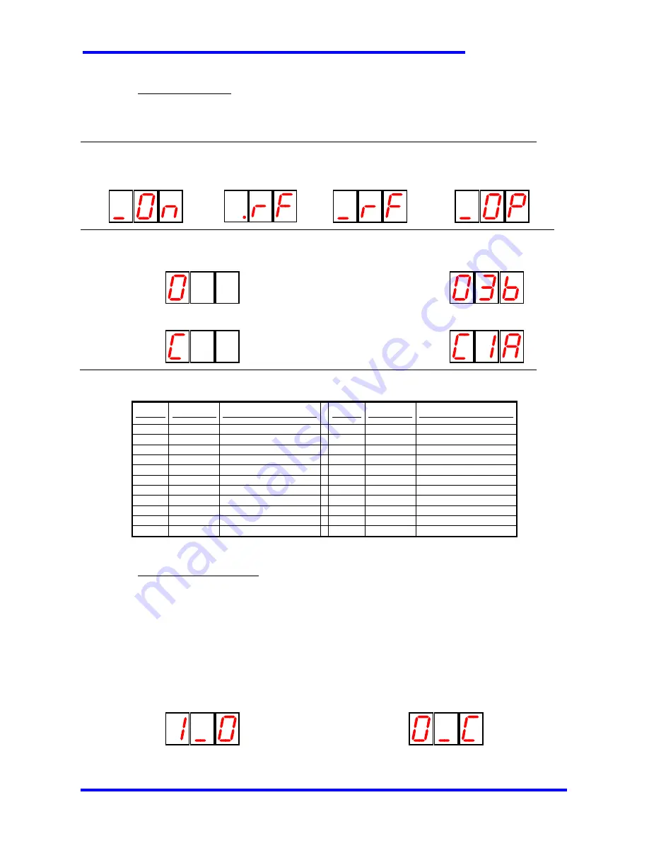
This is the menu for the normal operating mode, and is selected by default when the Receiver is powered on. The following
indications are displayed:
Normal operation:
No active operation
(waiting for RF signal)
No active operation
(RF signal detected)
(waiting for engagement)
No active operation
(RF signal detected)
(radio engaged)
_OP Operation in progress
Alarm indications (only in DBD / DBR systems):
Oxx Open circuit detected on valve xx when trying to
start a movement (see the table with all the alarm codes)
Example: open circuit
alarm on valve 3B:
Cxx Short circuit detected on valve xx when trying to
start a movement (see the table with all the alarm codes).
Example: short circuit
alarm on valve 1A:
The following table shows all the displayed alarm codes.
Display Alarm type Valve with active alarm
Display Alarm type Valve with active alarm
O1A
open circuit
EV on/off 1A
C1A
short circuit
EV on/off 1A
O1b
open circuit
EV on/off 1b
C1b
short circuit
EV on/off 1b
O2A
open circuit
EV on/off 2A
C2A
short circuit
EV on/off 2A
O2b
open circuit
EV on/off 2b
C2b
short circuit
EV on/off 2b
O3A
open circuit
EV on/off 3A
C3A
short circuit
EV on/off 3A
O3b
open circuit
EV on/off 3b
C3b
short circuit
EV on/off 3b
O4A
open circuit
EV on/off 4A
C4A
short circuit
EV on/off 4A
O4b
open circuit
EV on/off 4b
C4b
short circuit
EV on/off 4b
O5A
open circuit
EV on/off 5A
C5A
short circuit
EV on/off 5A
O5b
open circuit
EV on/off 5b
C5b
short circuit
EV on/off 5b
O_r
open circuit
VR (proportional)
C_r
short circuit
VR (proportional)
8.2.3
Digital Inputs Display Menu
This paragraph is applicable only to systems that implement digital inputs (e.g. limit switches).
This menu is accessed from the Normal Display Menu with the following procedure: push the proportional trigger to its maximum
level, then activate the 1A (first actuator from the left towards up) and 3B (third selector from the left towards down) functions
simultaneously for at least 5 seconds.
In this menu the states of the IN0 and IN1 inputs are displayed cyclically, with a 2.5s interval; each digital input can be in one of
the following states:
O open
C closed
Example: indication of the state “IN1 open”
Example: indication of the state “IN0 closed”


