Mounting Instructions
II_StraightBolt_02_eng Page 1 of 4
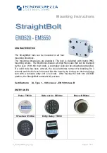
CHARACTERISTICS
The StraightBolt lock can be mounted in all four
mounting directions.
The mounting dimensions are standard. The lock is delivered with metric (M6)
mounting screws. The Electronics feature a 6-digit Main code that can be changed
by the user. With the main code, a secondary code can be activated and deleted.
If a valid code has been entered, the lock electronics remove the blocking for 3
seconds and the bolt can be moved into the housing by turning an internal driving
cam with a turnable entry unit or a knob. After moving the bolt into LOCKED
position, the StraightBolt automatically secures.
Certifications: UL Type 1 – VdS class 2 – EN1300 class B
ENTRY UNITS
Pulse: T6530
Delta series: DE20xx
Bravo: BR50xx
EM35•20 Technical Manual
CHARACTERISTICS
The StraightBolt lock can be mounted in all four mounting directions. The Basic Electronics
feature a 6-digit Main code that can be changed by the user. With the main code a secondary
code can be activated and deleted. If a valid code has been entered, the lock electronic removes
the blocking for 3 seconds and the bolt can be moved into the housing by turning an internal
driving cam with a turnable entry unit or a knob. After moving the bolt to LOCKED position, the
StraightBolt automatically secures.
ENTRY UNITS
The StraightBolt is compatible with the following NL LOCK Entry units (separate technical
descriptions for Entry units are available). Entry unit spindle/cable hole on the safe door does not
have to exceed 12 mm diameter
EM35•20 Technical Manual rev. 160223
© 2016 Lock Technology Page
!
of
!
1
2
Delta Series: DE20
Bravo: BR50
Premier: PI20
(with separate knob)
!
DE20-10 Technical Manual
CHARACTERISTICS
The Delta is a low profile electronic entry with “soft touch“ rubber keypad and metal
ring to be mounted with StraightBolt lock. Cable length is approximately 30 cm.
Additional battery box is required (sold separately).
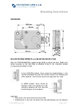
DIMENSIONS / MOUNTING INSTRUCTION
The diameter of the cable hole should be minimum 9 mm, maximum 12 mm. The
hole must be de-burred well to avoid damage to the cable.
Drill and tap door according to picture 1 drawing for the mounting plate
•
Fit the mounting plate (1) on door
using the 2x M4 mushroom-head
supplied screws (2) with "UP TO
ROTATE" oriented upwards
•
Cut spindle (5) length to exceed
8-10 mm lock mounting surface
•
Insert spindle in keypad so that
cable runs in the spindle groove.
•
Fit spring (4) and detent pin (3)
into the hole on the rear of the
keypad
•
Route the spindle through the
cable/spindle hole and move the
unit to the mounting adapters.
Rotate keypad 35-40° CCW until keypad can be fixed on the screw heads and
then rotate CW to straight up. Proceed with installing the lock.
The Delta entry unit can now not be removed!
DE20•10 Technical Manual rev. 110128
© 2011 Lock Technology BV Page 1 of 1
Delta
StraightBolt
Bolt work requirements
Lock bolt operations only allowed as described
into the drawing and max load should not
exceed 1KN.
Important:
•
Modifications to the lock (including lock bolt attachments) are not
allowed, and will void the manufacturer’s warranty and Standards
approvals.
•
No through holes on the safe door are allowed within the lock body area beside
the spindle/cable hole.
•
Lock body area should be protected against destructive attacks
ST series: ST40xx
Entry Delay: T8530


