7
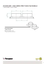
The DE.CS 25 dehumidifier is designed for installation in false ceilings with the possibility to convey the treated air or the
air to be treated. Typically placed in technical rooms or corridors, prefer supply ducts for the distribution of the treated air in
the different rooms; the return air does not necessarily have to be ducted and, in any case, make sure that all the rooms to
which the dehumidified air is sent have a return path for the humid air (return air vents, gaps between the door and the floor
above one centimetre, etc.).
Make sure that the machine is levelled, provide a siphon on the condensate drain in a lower position compared to the
bottom of the machine and avoid paths with sections that go uphill. Check the flow rate of the water to the coils, measuring
the supply air temperature; with low chilled water temperatures, the flow rate required to ensure neutral conditions also
decreases. The in-ceiling dehumidifier often becomes a trap for any air present in the hydraulic circuit; this condition can be
corrected by using the relief valve on the coupler side.
The fan has three speeds to be selected according to the ducting present: for long or complex ducting, the speed can be
increased to reach the nominal flow rate.
Attention: the dehumidifying power is not strictly linked to the air flow rate, therefore forcing the fan to operate at high speeds
when not necessary usually only leads to an increase in noise and electrical absorption and not performance!
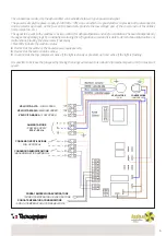
For the electrical connections, refer to the diagram.
The maintenance operations required for the proper operation of the dehumidifier are the periodic cleaning of the air filter on
the machine suction side: this intervention must be performed at regular intervals depending on the environment in which the
machine is placed but it is advisable not to allow more than 30 days to pass between the checks.
At the start of each season, check the actual circulation of water in the coils and the presence of residues in the tray or in the
condensate drain line.
filtro dell’aria in aspirazione della macchina: questo intervento va eseguito ad intervalli regolari in funzione dell’ambiente
in cui si trova la macchina ma si consiglia di non superare i 30 giorni tra i vari controlli.
Verificare ad ogni inizio stagione l’effettiva circolazione dell’acqua nelle batterie e la presenza di residui nella vaschetta
oppure nella linea di scarico condensa.
La struttura filtrante posta in aspirazione consente di estrarre il filtro nelle quattro direzioni facilitando la
manutenzione periodica: una volta scelto il lato d’estrazione spostare la vite ad azione manuale in tale posizione per
facilitare gli interventi di pulizia filtro.
Sequenza operativa:
Rimuovere la vite di fissaggio (1);
Sganciare il coperchio (2) dalla cornice di raccordo delle canalizzazioni;
Sfilare il filtro (3) eventualmente aiutandosi con un cacciavite.
Eliminare polvere e residui vari utilizzando un getto d’aria oppure
lavando il tessuto filtrane anche con semplice acqua;
Reinserire il filtro, riposizionare il coperchio facendo attenzione a
ripristinare l’aggancio con le asole della cornice e fissare con la vite.
Operating sequence:
Remove the screw (1);
Release the cover (2) from the ducting connection frame;
Remove the filter (3) with the help of a screwdriver if necessary.
Remove any dust and various residues using a jet of compressed air or by
washing the filter cloth even with plain water;
Reinsert the filter, refit the cover, taking care to reinsert it in the slots in the
frame, and secure it with the screw.
Nota: Il filtro opera una barriera meccanica al passaggio di particelle indesiderate, il colore sbiadito del tessuto non influisce
sulla funzione filtrante.
The filtering structure located on the suction side allows the filter to be removed from all four sides, thus facilitating periodic
maintenance: once the extraction side has been chosen, move the manual screw to that position to facilitate filter cleaning operations.
Note: The filter acts as a mechanical barrier against the passage of unwanted particles; the faded colour of the fabric does
not affect the filtering function.
Manuale DE.CS 25
Pagina 12 di 19
RIMOZIONE FILTRO
La struttura filtrante posta in aspirazione consente di estrarre il filtro nelle quattro
direzioni facilitando la manutenzione periodica:
una volta scelto il lato d’estrazione
spostare la vite ad azione manuale in tale posizione per facilitare gli interventi di
pulizia filtro.
Sequenza operativa:
- Rimuovere la vite di fissaggio (1);
- Sganciare il coperchio (2) dalla cornice di raccordo delle canalizzazioni;
- Sfilare il filtro (3) eventualmente aiutandosi con un cacciavite.
- Eliminare polvere e residui vari uti
lizzando un getto d’aria oppure lavando il
tessuto filtrane anche con semplice acqua;
- Reinserire il filtro, riposizionare il coperchio facendo attenzione a ripristinare
l’aggancio con le asole della cornice e fissare con la vite.
Nota: Il filtro opera una barriera meccanica al passaggio di particelle
indesiderate, il colore sbiadito del tessuto non influisce sulla funzione filtrante.
Summary of Contents for 30200010
Page 11: ...11 NOTE NOTES...

