background image

9

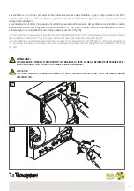
Il collegamento del ventilatore alla rete elettrica dev’essere effettuato tramite l’interruttore con l’apertura dei contatti non 

meno di 3 mm in tutti i poli. Il montaggio ed esempi di varianti diversi di collegamento del ventilatore sono illustrati nelle 

fig. 14 -30 e schemi 1-7.

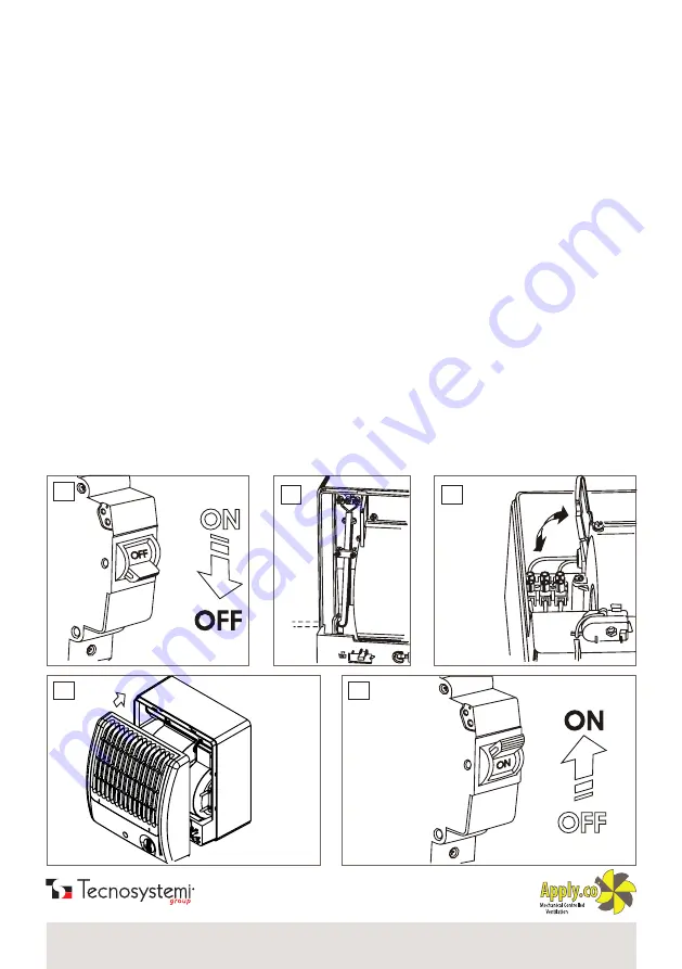
 Per il collegamento del ventilatore alla rete elettrica è necessario:

• 

far passare i fili conduttori tramite il finestrino nella parte inferiore del corpo, poi perforare il coperchio del corpo nel 

caso di collegamento laterale del filo (fig.15);

• 

togliere isolamento dalle estremità dei fili lungo 7-8 mm, poi inserirli nei morsetti corrispondenti: procedere con il 

serraggio delle viti (fig. 16)

• 

bloccare i fili con la piastra (fig.15)

• 

inserire il coperchio al ventilatore (fig. 17)

• 

accendere la tensione di alimentazione del ventilatore (fig.18);

COLLEGAMENTO DEL VENTILATORE ALLA RETE

/ CONNECTING THE FAN TO THE MAINS

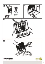
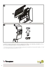
14

15

17

18

16

The fan must be connected to the mains via a switch with a contact opening of no less than 3 mm in all poles. The installation and 

examples of different fan connection variants are shown in fig. 14-30 and diagrams 1-7.

 To connect the fan to the mains, it is necessary to:

• 

pass the conductor wires through the window in the lower part of the body, then drill a hole in the body cover in the case 

of lateral wire connection (fig.15);

• 

remove 7-8 mm of insulation from the ends of the wires, then insert them into the corresponding terminals: then tighten 

the screws (fig. 16)

• 

block the wires with the plate (fig.15)

• 

insert the cover on the fan (fig. 17)

• 

switch on the supply voltage to the fan (fig.18);

Summary of Contents for Apply.co 11104029

Page 1: ...a 31029 Vittorio Veneto Treviso Italy Phone 39 0438 500044 Fax 39 0438 501516 Numero Verde 800 904474 only for Italy email info tecnosystemi com C F P IVA R I TV IT02535780247 Cap Soc 5 000 000 00 i v REV 05 04 08 2022 COD C20002871 ASPIRATORE ELETTRICO CENTRIFUGO CANALIZZABILE DUCTABLE CENTRIFUGAL ELECTRIC EXTRACTOR cod 11104029 ...

Page 2: ...vernale L area di passaggio non deve contenere sostanze collose fibrose polvere ed altre impurità con elementi duri più di 100 mg m3 The centrifugal fan is designed for ceiling or wall installation for ventilation in utility and public rooms rooms in homes offices shops kitchens bathrooms and other rooms with heating in winter The passage area must not contain sticky fibrous substances dust and ot...

Page 3: ...ATO FORBIDDEN L utilizzo dei ventilatori fuori l intervallo delle temperature ed anche nei locali con la presenza in area delle sostanze aggressive e nell ambiente esplosivo The use of the fans outside the temperature range and also in rooms with the presence of aggressive substances in the air and in an explosive environment ATTENZIONE ATTENTION Assicurarsi inoltre che l impianto sia fuori tensio...

Page 4: ...scita è installata la valvola di ritorno Il led indica che il ventilatore si trova nel regime di lavoro 2 COSTRUZIONE DEL VENTILATORE FAN CONSTRUCTION The fan fig 2 consists of a body inside which the electric motor with the fan is secured The fan is inserted in the scroll casing Moreover the removable cover is installed on the body with the grill attached Install the filter in the free space betw...

Page 5: ... incasso è illustrata nella fig 12 il montaggio a soffitto è illustrato nella fig 13 Il supporto non viene presentato nella fornitura di base MONTAGGIO E PREPARAZIONE AL LAVORO ASSEMBLY AND PREPARING FOR WORK The fan is designed for both wall and ceiling installation Examples of different fan installation variants are shown in fig 3 8 the overall dimensions and the way it is attached are indicated...

Page 6: ...TE SUL SUPPORTO BUILTINTOTHEWALLONTHESUPPORT 3 VENTILATORE DA PARETE WALLFAN MONTAGGIO E PREPARAZIONE AL LAVORO ASSEMBLY AND PREPARING FOR WORK 5 INCORPORATONELLAPARETECONLASCHIUMADIMONTAGGIO BUILTINTOTHEWALLUSINGTHESPECIALFOAM ...

Page 7: ...ICCHIA CIECA BUILTINTOTHERECESS 7 FISSATO CON L AIUTO DEL SUPPORTO A SOFFITTO SECUREDWITHTHEHELPOFTHECEILINGSUPPORT 8 MONTATO AL SOFFITTO NELLA NICCHIA PREPARATA IN ANTICIPO INSTALLEDONTHECEILINGINTHEPREVIOUSLYPREPAREDRECESS ...

Page 8: ...8 10 11 12 9 13 SEQUENZA DI MONTAGGIO ASSEMBLY SEQUENCE ...

Page 9: ...a piastra fig 15 inserire il coperchio al ventilatore fig 17 accendere la tensione di alimentazione del ventilatore fig 18 COLLEGAMENTO DEL VENTILATORE ALLA RETE CONNECTING THE FAN TO THE MAINS 14 15 17 18 16 The fan must be connected to the mains via a switch with a contact opening of no less than 3 mm in all poles The installation and examples of different fan connection variants are shown in fi...

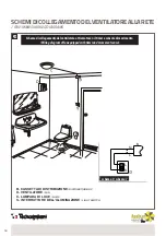
Page 10: ...assetta di distribuzione Drawingoftheroomwithlightconnectionviadistributionbox B CASSETTA DI DISTRIBUZIONE DISTRIBUTION BOX C LAMPADA DI LUCE LAMP D INTERRUTTORE DI LUCE LIGHT SWITCH schema 1 diagram1 SCHEMIDICOLLEGAMENTODELVENTILATOREALLARETE FAN MAINS WIRING DIAGRAMS ...

Page 11: ...tore alla presa di corrente Drawingoftheroomwithfanconnectiontopoweroutlet B CASSETTA DI DISTRIBUZIONE DISTRIBUTION BOX D VENTILATORE FAN E PRESA DI CORRENTE POWER OUTLET schema 2 diagram2 SCHEMIDICOLLEGAMENTODELVENTILATOREALLARETE FAN MAINS WIRING DIAGRAMS ...

Page 12: ...erruttore Wiringdiagramoffanequippedwithswitch B CASSETTA DI DISTRIBUZIONE DISTRIBUTION BOX D VENTILATORE FAN C LAMPADA DI LUCE LAMP S INTERRUTTORE DELL ILLUMINAZIONE LIGHT SWITCH schema 3 diagram3 SCHEMIDICOLLEGAMENTODELVENTILATOREALLARETE FAN MAINS WIRING DIAGRAMS ...

Page 13: ...erno Wiringdiagramoffanwithoutbuilt inswitch viaexternalswitch D VENTILATORE FAN C LAMPADA DI LUCE LAMP S INTERRUTTORE DELL ILLUMINAZIONE LIGHT SWITCH SD INTERRUTTORE DEL VENTILATORE ESTERNO EXTERNAL FAN SWITCH schema 4 diagram4 SCHEMIDICOLLEGAMENTODELVENTILATOREALLARETE FAN MAINS WIRING DIAGRAMS ...

Page 14: ...mpada di luce al ventilatore attrezzato con il timer timer con il sensore di umidità controllato da un solo interruttore Wiringdiagramoflamptofanequippedwithtimer timer withmoisturesensorcontrolledbyasingleswitch B CASSETTA DI DISTRIBUZIONE DISTRIBUTION BOX D VENTILATORE FAN C LAMPADA DI LUCE LAMP S INTERRUTTORE DELL ILLUMINAZIONE LIGHT SWITCH SCHEMIDICOLLEGAMENTODELVENTILATOREALLARETE FAN MAINS W...

Page 15: ...DEVE ESSERE EFFET TUATA SOLTANTO CON LA RETE DI ALIMENTAZIONE DISINSERITA 24 25 ATTENTION THE TIMER DIAGRAM IS UNDER THE MAINS VOLTAGE IT MUST BE ADJUSTED ONLY WITH THE MAINS VOLTAGE DISCONNECTED Il ventilatore con il timer provvede all interruzione automatica del ventilatore dopo il tempo indicato dal timer nell intervallo da due a trenta minuti viene regolato dal potenziamento T con il giro in s...

Page 16: ... DI DISTRIBUZIONE DISTRIBUTION BOX D VENTILATORE FAN C LAMPADA DI LUCE LAMP S INTERRUTTORE DELL ILLUMINAZIONE LIGHT SWITCH VARIANTE MONTAGGIO A SOFFITTO SCHEMIDICOLLEGAMENTODELVENTILATOREALLARETE FAN MAINS WIRING DIAGRAMS schema 6 diagram6 Con l interruzione della lampada di luce il ventilatore funziona durante il tempo indicato dal timer When the lamp is switched off the fan continues to work for...

Page 17: ...r fig 28 27 28 ATTENZIONE LO SCHEMA DEL TIMER SI TROVA SOTTO LA TENSIONE DI RETE LA REGOLAZIONE DEVE ESSERE EFFET TUATA SOLTANTO CON LA RETE DI ALIMENTAZIONE DISINSERITA ATTENTION THE TIMER DIAGRAM IS UNDER THE MAINS VOLTAGE IT MUST BE ADJUSTED ONLY WITH THE MAINS VOLTAGE DISCONNECTED The fan with timer automatically stops after the time indicated by the timer in the interval between two and thirt...

Page 18: ... movimento Wiringdiagramoffanequippedwithtimerandmovementsensor B CASSETTA DI DISTRIBUZIONE DISTRIBUTION BOX D VENTILATORE FAN C LAMPADA DI LUCE LAMP S INTERRUTTORE DELL ILLUMINAZIONE LIGHT SWITCH schema 7 schema7 SCHEMIDICOLLEGAMENTODELVENTILATOREALLARETE FAN MAINS WIRING DIAGRAMS ...

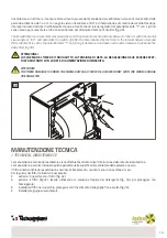
Page 19: ...io è necessario estrarre il coperchio con il filtro fig 32 estrarre il filtro fig 33 lavarlo utilizzando la soluzione tiepida del detergente fig 34 poi proseguire con l asciugatura installare il filtro nel coperchio proseguire con l inserimento della griglia fino a scatto fig 35 installare la griglia sul ventilatore The fan with timer and movement sensor switches on if the person moves at a distan...

Page 20: ... da 5 C fino a 40 C ed umidità relativa dell area non più del 60 con 20 C La presenza nell aria di vapori acidi sali alcalini ed altre sostanze aggressive non è accettabile ATTENZIONE Il produttore non e responsabile dei danni causati utilizzando il ventilatore con destinazione sbagliata oppure nel caso di grave intervento meccanico Il proprietario del ventilatore deve attenersi alle istruzioni RE...

Page 21: ...21 31 32 33 34 ...

Page 22: ...ruttore a una temperatura compresa tra 5 C e 40 C e a un umidità dell aria relativa non superiore all 80 con T 25 C The extractor must be stored in the original packaging supplied by the manufacturer at a temperature between 5 C and 40 C and relative humidity below 80 at T 25 C ...

Page 23: ...sta di danni La garanzia non copre la sostituzione dei componenti che risultano danneggiati per trasporto non idoneo installazione non conforme a quanto specificato in questo manuale di installazione uso e manutenzione la non osservanza delle specifiche tecniche di prodotto quant altro non riconducibile a vizi originari del materiale o di produzione a condizione che il reclamo del cliente sia cope...

Page 24: ...emi com via dell Industria 2 4 Z I San Giacomo di Veglia 31029 Vittorio Veneto Treviso Italia Tel 39 0438 500044 Fax 39 0438 501516 email info tecnosystemi com C F P IVA R I TV IT02535780247 Cap Soc 5 000 000 00 i v 800 904474 ONLY FOR ITALY WATCH OUR INSTITUTIONAL VIDEO I I S S O O 9 9 0 0 0 0 1 1 S S Y YS ST TE EM M C CE ER RT TI IF FI IC CA AT TI IO O N N ...

Reviews: