background image

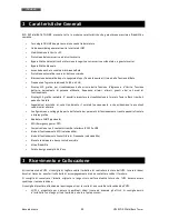
ITALIANO 

Manuale utente 

42


UPS EVO DSP MM Rack Tower 


6


Installazione Elettrica 


L'installazione  elettrica,  nonostante  la  sua  semplicità,  deve  essere  eseguita 
esclusivamente da elettricisti qualificati. Seguire scrupolosamente tutte le norme locali 
e  nazionali  (in  ITALIA  le  norme  CEI)  per  le  connessioni  d'Ingresso  e  d’Uscita  e  per  il 
corretto dimensionamento dei cavi d'Ingresso e d’Uscita. 

Per la sicurezza degli operatori occorre posizionare degli interruttori esterni tra la linea 
elettrica  d’Ingresso  e  la  linea  d’Ingresso  dell’UPS,  e  tra  le  linee  d’Uscita  dell’UPS  e 
carichi.  Gli  interruttori  hanno  la  funzione  di  protezione  e  sicurezza  e  devono  essere 
scelti con la specifica di corrente di dispersione inferiore a 30 mA. 

Per i collegamenti d’Ingresso/Uscita utilizzare esclusivamente i cavi in dotazione con il 
prodotto o cavi con analoghe caratteristiche.  

In caso contrario TECNOWARE declina ogni sua responsabilità. 

 
I  modelli  EVO  DSP  MM  RACK  TOWER    sono  costituiti  da  un’unità  singola  che  contiene  sia  l’elettronica  che  le 
batterie. 


Prima di avviare la procedura d'installazione, accertarsi che: 

1. La linea elettrica d’Ingresso all’UPS sia scollegata. 

2. L’UPS sia completamente spento (solo in tal caso il display LCD grafico è spento). 


6.1


Installazione  

Svolgere le seguenti operazioni: 

1.


Tramite il cavo di alimentazione in dotazione collegare la presa d’Ingresso rete (vedi figura 4) ad una 

presa 

di alimentazione elettrica che deve avere obbligatoriamente una connessione a terra secondo le norme 
vigenti

. Verificare accuratamente il collegamento a terra della presa d’alimentazione elettrica. 

2.


Collegare  i  dispositivi  da  alimentare  alle  prese  d’Uscita  dell’UPS,  utilizzando  i  cavi  d’uscita  in  dotazione. 
Assicurarsi che tutti i dispositivi collegati siano spenti. 

3.


Solo se occorre utilizzare un Box Batterie esterno:  


Si consiglia di utilizzare ESCLUSIVAMENTE i Box Batterie forniti da TECNOWARE. In caso 
contrario TECNOWARE declina ogni sua responsabilità. 

Prima  di  svolgere  qualsiasi  operazione  accertarsi  che  l'interruttore  Batterie  del  Box 
Batterie sia in posizione “OFF”. 


3.1.


Rimuovere  la  copertura  metallica  (#9)  sul  retro  dell’UPS  (vedi  figura  4),  per  accedere  al  Connettore 
Box Batterie. 

3.2.


Collegare il Box Batterie al connettore Box Batterie. 

3.3.


Portare l’interruttore Batterie del Box Batterie in posizione “ON”. 


Summary of Contents for EVO DSP MM 1.3 Rack Tower

Page 1: ...Uninterruptible Power Supply EVO DSP MM 1 3 Rack Tower EVO DSP MM 2 6 Rack Tower EVO DSP MM 4 0 Rack Tower User s manual Manuale utente...

Page 2: ......

Page 3: ...2 6 Electrical Installation 13 6 1 Installation 13 7 First Start Up 14 8 Functioning 15 8 1 Turning ON and OFF 15 8 2 Low Battery and Automatic Restart 15 8 3 Load Testing 16 8 4 Manual Static Bypass...

Page 4: ...1 6 Installazione Elettrica 42 6 1 Installazione 42 7 Prima Accensione 43 8 Funzionamento 44 8 1 Accensione e Spegnimento 44 8 2 Fine Autonomia e Riaccensione Automatica 44 8 3 Controllo del Carico 45...

Page 5: ...sonnel authorized by TECNOWARE TECNOWARE declines any responsibility if this warning is disregarded The electric installation has to be done by qualified personnel Follow all the Safety Standards CEI...

Page 6: ...y an Automatic Bypass that directly connects the AC Input line with its outlets EVO DSP MM RACK TOWER models are factory equipped with RS 232 and USB interfaces which may be used for notify to a compu...

Page 7: ...icating alarm situations Available settings of all the UPS parameters by user through front panel pushbuttons and graphic LCD panel SNMP Adapter optional EPO Emergency Power OFF Communication with the...

Page 8: ...eave at least 10 cm of unobstructed space all around the UPS in order to keep it properly ventilated Do not obstruct ventilation holes Do not insert objects or pour liquids in the ventilation holes Do...

Page 9: ...inds the Mains OFF condition due to a Blackout or Overvoltage Brownout it then switches into Battery mode In this case the batteries supply the required Output power thanks to the DC AC conversion car...

Page 10: ...fied by The graphic LCD panel shows the functioning during Stand by mode 4 5 ECO Mode It is possible to select the ECO mode to save energy and to increase the efficiency of the UPS The ECO mode uses t...

Page 11: ...The Converter Frequency mode is identified by The graphic LCD panel shows the functioning during Converter Frequency mode The CF characters are ON 5 EXTERNAL DESCRIPTION 5 1 Front Panel The front pane...

Page 12: ...nel Please refer to figure 3 Figure 3 Graphic LCD Panel Battery info Load Info Input output and Battery info UPS status Warning Fault Info Setting Operation Backup Time Info Load info UPS status Batte...

Page 13: ...UPS alarm is disabled muted Output Voltage information Indicates the Output Voltage or Output Frequency or Battery Voltage V Output Voltage and Battery Voltage Hz Output Frequency Load information In...

Page 14: ...easurements on the graphic display by pressing the SELECT button it is possible to choose the electrical parameter to be displayed Input Voltage Input Frequency Battery Voltage Output Voltage Output F...

Page 15: ...T connectors to protect and filter a phone line an ADSL or a LAN 4 EPO Emergency Power OFF connector 5 Input Circuit Breaker it goes off in Overload or short circuit condition push the external button...

Page 16: ...ks normally If you want to use an external switch to turn OFF the UPS by EPO then remove the short circuit from the EPO terminals and connect the switch to the EPO terminals as described in the figure...

Page 17: ...re be sure that 1 The AC Input Voltage for the UPS has been removed 2 The UPS is completely OFF only if graphic LCD panel is OFF 6 1 Installation We advise you to follow the steps below explained 1 Th...

Page 18: ...ed to the UPS outputs have the main switch in OFF position 2 Restore the AC Input line for the UPS be sure that the AC utility power is available and that its voltage and frequency are within the spec...

Page 19: ...he UPS If the ON MUTE button is pressed when AC Input line is not present the UPS switches ON even and works in Battery mode after some seconds If the OFF ENTER button is pressed when AC Input line is...

Page 20: ...k within range the UPS switches automatically to the Normal mode Make sure that the UPS never indicates Overload condition Do not connect a load greater than rated value to the UPS see POWER specifica...

Page 21: ...buzzer beeps once every second it means that there are some problems for UPS operation Users can get the Fault code from graphic LCD panel Please check the Troubleshooting chapter for details Below y...

Page 22: ...ft Start failure 11 None Over Temperature 41 None High Inverter Voltage 12 None Overload 43 Fault Table 9 Communication Interfaces The UPS is factory equipped with RS232 and USB Communication Interfac...

Page 23: ...5 Upper Limit come back to Line mode 290 Vac 5 Nominal Frequency 50 60 Hz automatic selection Frequency Range Normal mode 47 53 Hz 57 63 Hz Input Power Factor 0 99 at 100 Load OUTPUT Nominal Voltage S...

Page 24: ...ection level IP 20 Cooling Fan cooling Audible Noise at 1 meter 45 dBA STANDARDS Safety EN 62040 1 1 EN 60950 1 Performance EN 62040 3 EMC EN 62040 2 category C2 Product certification CE COMMUNICATION...

Page 25: ...ings of the UPS exception for the function of display rotation There are 8 program setting 00 Exit from Settings 01 Output Voltage Setting Interface Setting For 208 220 230 240Vac models you may choos...

Page 26: ...If converter mode enable you may choose the following output frequency CF 50 presents output frequency is 50Hz CF 60 presents output frequency is 60Hz 04 ECO Enable Disable Interface Setting ENA ECO...

Page 27: ...ay is horizontal TOE the LCD display is vertical 10 Acceptable Input Voltage Range Setting Interface Setting For 208 220 230 240Vac models you may choose the following Acceptable input voltage range 1...

Page 28: ...ter 7 First Start Up before using it again Please keep in mind that the batteries must be recharged at least once a month Take in mind that batteries are recharged automatically if the UPS is ON and w...

Page 29: ...al plastic panel to accede to the vain contains the batteries as reported in the left image Disconnect the battery connector as reported in the left image Extract the drawer that contains the batterie...

Page 30: ...ersonnel Original safety characteristics might not be if for example the UPS has visible damage or irregular operation Position the batteries in the drawer as reported in the left image Close the draw...

Page 31: ...ed technical personnel authorized by TECNOWARE TECNOWARE declines any responsibility if this warning is disregarded SYMPTOM POSSIBLE CAUSE ACTION TO SOLVE No indication and or alarm on the front panel...

Page 32: ...PS shuts down automatically Remove excess loads from UPS Output and restart it Fault code is shown as 14 the icon lights on LCD display and alarm beeps continuously The UPS shuts down automatically be...

Page 33: ...posal or an improper use of the same or of any parts can be damaging for the environment and for human health A correct waste disposal of products having the dustbin symbol marked by a cross help to a...

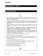
Page 34: ...lizzato ed autorizzato da TECNOWARE In caso contrario TECNOWARE declina ogni sua responsabilit L installazione elettrica nonostante la sua semplicit deve essere eseguita esclusivamente da elettricisti...

Page 35: ...WER e collega direttamente la linea elettrica d Ingresso alle uscite EVO DSP MM RACK TOWER dotato d interfacce di comunicazione RS232 e USB che possono essere utilizzate per segnalare ad un generico e...

Page 36: ...ack tramite il pannello frontale Segnalazioni acustiche di vario tipo durante il normale funzionamento e che evidenziano le eventuali condizioni di allarme Configurazione e settaggio da parte dell ute...

Page 37: ...scelto rientri in tali specifiche Durante il normale funzionamento l UPS emette una quantit minima di calore perci necessario lasciare uno spazio libero di almeno 10 cm sia lateralmente che sul retro...

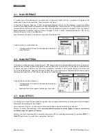
Page 38: ...dovuta ad un black out oppure ad una variazione dell ampiezza della Tensione di Rete oltre le specifiche allora passa nel modo Batteria In questo caso sono le batterie che forniscono la potenza necess...

Page 39: ...mpletamente dopo alcuni secondi Il modo Stand by caratterizzato da Il display grafico LCD mostra il funzionamento durante il modo Stand by 4 5 Modo ECO possibile selezionare il modo ECO per risparmiar...

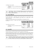
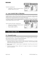
Page 40: ...izzato da Il display grafico LCD mostra il funzionamento durante il modo Convertitore di Frequenza Il display visualizza i caratteri CF 5 Descrizione Esterna 5 1 Pannello Frontale Il pannello frontale...

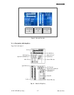
Page 41: ...fico Prego riferirsi alla figura 3 Figura 3 Pannello LCD grafico Carica Batterie Carico Info Tensione Ingresso Uscita Batterie Stato UPS Allarmi Errori Impostazioni Tempo di Backup Carico Stato UPS Ca...

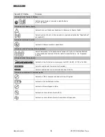
Page 42: ...la Tensione d Uscita Output Indica l Ampiezza e la Frequenza della Tensione d Uscita e la Tensione Batterie V Ampiezza della Tensione d Uscita e della Tensione Batterie Hz Frequenza d Uscita Informazi...

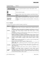
Page 43: ...display grafico tramite la pressione del tasto SELECT possibile scegliere la grandezza elettrica che viene visualizzata sul display possibile visualizzare la Tensione d Ingresso la Frequenza d Ingres...

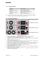
Page 44: ...IN OUT per proteggere e filtrare una linea telefonica ADSL o LAN 4 Connettore EPO Emergency Power OFF 5 Interruttore Termico d Ingresso Rete l interruttore scatta in caso di sovraccarico o cortocircu...

Page 45: ...mente Se si vuole utilizzare un interruttore esterno per attivare lo spegnimento EPO allora rimuovere il cortocircuito dai terminali e collegare l interruttore ai terminali come descritto nella figura...

Page 46: ...procedura d installazione accertarsi che 1 La linea elettrica d Ingresso all UPS sia scollegata 2 L UPS sia completamente spento solo in tal caso il display LCD grafico spento 6 1 Installazione Svolg...

Page 47: ...trollare che la sua ampiezza e frequenza siano all interno delle specifiche 3 In seguito al punto 2 l UPS accende il display grafico e si pone in uno stato di attesa Stand by durante il quale l UPS no...

Page 48: ...i Rete elettrica in Ingresso l UPS si accende ugualmente dopo alcuni secondi attiva l Inverter e comincia a funzionare nel modo Batteria Se premuto il pulsante OFF ENTER quando non presente la Tension...

Page 49: ...do di funzionamento Normale Controllare che l UPS non indichi mai la condizione di Overload Non applicare all UPS un carico maggiore del valore nominale di targa vedere le specifiche di POTENZA del ca...

Page 50: ...allarme acustico una volta ogni secondo I tipi di Allarme che si possono verificare durante il normale funzionamento sono elencati nella Tabella Allarmi sotto riportata Per ogni allarme indicato anch...

Page 51: ...Tensione Batteria troppo bassa 28 Guasto Soft Start Inverter 11 Nessuno Alta Temperatura 41 Nessuno Alta Tensione Inverter 12 Nessuno Overload 43 Tabella Fault 9 Interfacce di Comunicazione L UPS dot...

Page 52: ...iore rientro da modo Batteria 290 Vac 5 Frequenza Nominale 50 60 Hz selezione automatica Range Frequenza modo Normale 47 53 Hz 57 63 Hz Fattore di Potenza d Ingresso 0 99 con carico al 100 USCITA Tens...

Page 53: ...e IP 20 Raffreddamento Forzato tramite ventole Rumorosit ad 1 metro 45 dBA CONFORMIT ALLE NORME Sicurezza EN 62040 1 1 EN 60950 1 Prestazioni EN 62040 3 EMC EN 62040 2 categoria C2 Certificazione del...

Page 54: ...del display Ci sono 8 possibili settaggi 00 Uscita dai Settaggi 01 Impostazione Tensione di Uscita Visualizzazione Settaggio Per I modelli da 208 220 230 240Vac si possono impostare le seguenti tensi...

Page 55: ...i frequenza attiva possibile impostare le seguenti frequenze di uscita CF 50 la frequenza d uscita presente 50Hz CF 60 la frequenza d uscita presente 60Hz 04 Modalit ECO Attiva Disattiva Visualizzazio...

Page 56: ...zontalmente TOE il display visualizzato verticalmente 10 Impostazione Range Tensione d Ingresso Visualizzazione Settaggio Per I modelli da 208 220 230 240Vac possibile impostare I seguenti range della...

Page 57: ...procedura di Prima Accensione descritta nell omonimo capitolo di questo manuale Tenere comunque presente che le batterie vanno ricaricate almeno 1 volta al mese Si ricorda che l UPS ricarica le batter...

Page 58: ...plastica per accedere al vano contenente le batterie come riportato nella figura sulla sinistra Scollegare il connettore batterie come riportato nella figura sulla sinistra Estrarre il cassetto conten...

Page 59: ...originali possono venire meno se per esempio L UPS presenta dei danni visibili o un funzionamento anomalo Posizionare le batterie nel cassetto come riportato nella figura sulla sinistra Chiudere il ca...

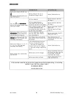
Page 60: ...asi tipo devono essere compiuti solo da personale tecnico specializzato ed autorizzato da TECNOWARE In caso contrario TECNOWARE declina ogni sua responsabilit ANOMALIA POSSIBILE CAUSA AZIONI PER RISOL...

Page 61: ...troppo a lungo L UPS si disattivato automaticamente segnalando una situazione di guasto Scollegare il carico eccessivo dall Uscita UPS e riaccendere l UPS Sul display grafico visualizzato il codice di...

Page 62: ...orretto del prodotto o l uso improprio dello stesso o di sue parti dannoso per l ambiente e per la salute umana Il corretto smaltimento dei prodotti recanti il simbolo del bidone segnato da una croce...

Page 63: ...ved All trademarks are property of their respective owners TECNOWARE s r l Via Montetrini 2E Loc Molino del Piano 50065 Pontassieve FI Italy www tecnoware com This manual has been printed and edited b...

Page 64: ......

Page 65: ......

Page 66: ...TECNOWARE s r l www tecnoware com...

Reviews: