User’s Manual
24
UPS EVO DSP TT
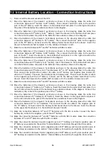
In case this communication cable is removed or damaged during parallel operation and the
communication is lost, then the slave UPS which can not communicate with the master UPS and it
shall disconnect its output and maintain the OFF condition. The other UPSs shall continue their
normal operation.
In such a case, this UPS should be turned off completely in order to insert its communication
cable again and then switched on again. Do not try to insert the communication cable while it
is operating.
4
All breakers (F1, F2, F3, F4 (optional), F5 and F6) should be in “OFF”/“0” position.
5
Switch “ON”/“1” the Input circuit breaker (F1) of the first UPS (“Master” or “Number 1” labeled
UPS), Inrush circuit breaker (F6) should be in “OFF”/“0” position. (Note: if the UPSs are not factory
parallel configured, then any of the UPSs can be switched on but one should be configured as
master and the remaining UPSs as slave which will be explained in detail in the following section).
6
Go to the “CONFIGURATION” section from the front panel menu, select “MODE” part and check
that “PARALLEL-1” name is displayed; otherwise change from “SINGLE” to “PARALLEL-1” name by
using the keys. Please check this during commissioning.
7
By using DOWN key on the same menu enter to “N NUMBER” part and select “N” number.
The Parallel System operate according to redundancy principle.
N is the minimum UPS qty that is required to supply the load where each UPS operates in full
load condition. Then (UPS qty) – (N) becomes the redundant UPS qty in the Parallel System.
On each UPS, the value N should be same and correctly entered.
“N” can be defined as 1, 2 or 3.
8
After defining the UPS name and N value from the “CONFIGURATION” menu, switch off the UPS and
similarly configure the other Parallel UPSs in the Parallel System. After this switch off each UPS
again. Maximum 4pcs of UPS can be connected in parallel and each UPS name should be different
(note: if the UPSs are factory parallel configured then each UPS name has been already defined,
please check and control this).
Configuring the Parallel UPSs with same name may cause serious damage during
operation. Make sure that each Parallel UPS is configured with different names.
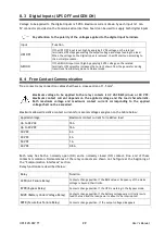
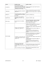
The UPS shows the condition of “Redundancy Lost” through the “REDUND. LOST” alarm
message. “REDUND. LOST” alarm message is just a warning alarm stating that the load
amount shared on the remaining UPSs is more now, after the failure of one UPS or after a
power increase on the load side. This alarm shall not affect the normal operation of the
Parallel System. It indicates that there is not anymore a redundant UPS in the Parallel
System. In case of a failure on one of the remaining UPSs, the Parallel System will either
go to Overload, Bypass condition or will shut down totally depending on the UPS quantity
in the Parallel System.
The following table shows the condition of “Redundancy Lost” for some typical Parallel Systems.
Load% is displayed on the LCD display of each UPS.
Total Parallel UPSs
quantity
N (minimum UPSs to
support the load)
Number of
redundant UPSs
Condition of “Redundancy
Lost”
2
1
1
Load % > 50%
3
2
1
Load % > 66%
4
3
1
Load % > 75%
4
2
2
Load % > 50%
Summary of Contents for EVO DSP TM
Page 1: ...Uninterruptible Power Supply EVO DSP TM 10 30kVA User s manual ...
Page 2: ......
Page 42: ......
Page 43: ......


