background image


18

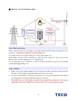
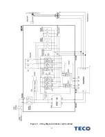
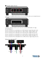
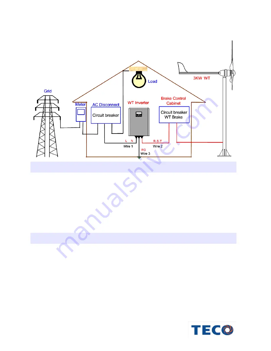
 Wind Power System Wiring Description 

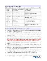
Power Wire Size Selection


Please connect electrical wire according to each contact marked with description. Regulated wire size 
as follows

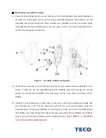
(Detailed wiring diagram as Figure 8,Figure 9)


AC output wire use a size at least 12AWG(or 3.5 mm

2

) black copper wire.     

Wind turbine wires use at least 12AWG(or 3.5 mm

2

) and above copper wire, these wires to be of 

different color in order to distinguish R, S, T 3-phase power. 
It is recommended to use 12 AWG(or 3.5 mm

2

) and above yellow/green copper wire on machine 

housing earthing(grounding) wire. 
 

Notice of Wiring 

¾


Before wiring, please finish installation of the wind power inverter, meanwhile, check and ensure 
that there is no fuse breaker of main distribution board is in close status.   

¾


In order to ensure quality of electrical wiring. Please use a wire size recommended in this manual 
and in accordance with wiring standard of electrical regulations.


¾


The GREEN wire of wind turbine is neutral wiring output from generator, it’s for special 

application. Please leave GREEN wire isolated, don’t wire it to any conductive goods. 

Summary of Contents for 3kW Grid-Tie HAWT

Page 1: ...0 Table of Contents User M User Manual ...

Page 2: ...d Power Inverter Description 9 1 5 Wind Power System Operation 9 Chapter 2 Installation of Wind Power System 11 2 1 Installation of Wind Turbine 11 2 2 Installation of Grid tied Wind Power Inverter 15 Chapter 3 Wind Power System Operation 25 3 1 Start Test 25 3 2 Instruction of Grid tied Wind Power Inverter 25 Chapter 4 Protection 27 4 1 Electromagnetic Brake Protection 27 4 2 High Wind Protection...

Page 3: ...k may weaken the strength of tower or support frame structure and result in casualty death or losses of property 10 Lack of maintenance in any part of the system improper operation of the wind energy power system and loose of components or parts may cause casualty death or losses of property 11 Please avoiding approaching the blade due to high speed rotary blade due to the high possibility causing...

Page 4: ...d for safe installation Location of tower tower and tower foundation must be professionally designed Soil and wind field status must be put into consideration when selecting a location Tower must keep far away from buildings neighboring properties or electrical power lines Do not attempt to climb the tower only experienced personnel with adequate safety equipment is allowed to climb the tower It i...

Page 5: ...cause a low voltage shock whenever the rotor is turning Caution must be implemented at all times to avoid electrical shock 10 Please do not install wind power system near cliffs or precipices or on sharp hills such that the wind does not travel horizontally through the rotor 11 The weight distribution of the system is specially balanced Any change of the system weight and balance especially the ta...

Page 6: ... mono tower kit and guyed tubular tilt tower kit For tower installation procedures please refer to the Chapter 2 1 Wind Turbine Specifications Rotor diameter 2 5 m Total weight 58 kg Start up wind Speed 2 5 m s Furl Protection Start 13 5 m s Cut in wind Speed 2 8 m s Cut out wind Speed 13 5 m s Rated wind Speed 13 5 m s Rated output 3000W 13 5 m s Survival Wind Speed 50 m s Rotor RPM 145 780rpm Ma...

Page 7: ... turbine assembly Blades Generator Nacelle and Tail Assembly Complete Assembly Figure 2 Wind turbine major Components Tail Fin Generator Casing Tower Mount Adapter Spinner Tail Boom Nacelle Blade Central Body Assembly ...

Page 8: ... rectified to direct current or connected to power grid through a grid tied device C Central Body Assembly The central body assembly consists of the blade hub generator casing and the nacelle It is the main structural backbone of the rotor system the generator the yaw bearings slip ring assembly the tail and the tower mount The yaw bearings allow the wind turbine to turn around the top of the towe...

Page 9: ...ower Inverter Output power 3000W Input Nominal voltage 180VAC Working range 30 300 VAC MPPT range 50 250 VAC Max input current 18A Output Operational voltage 220VAC 230VAC 240VAC Maximum Output current 14A Operational frequency 50 60Hz auto select Power factor 0 99 Full Load Current distortion 4 Maximum Efficiency 95 Anti Islanding VDE 0126 CE EN50178 IEC62103 Environment Protection degree IP43 Op...

Page 10: ...n and energy saving 1 5 Wind Power System Operation A Normal Operation The generator of wind power system should begin to generate electricity when the wind speed reaches approximately 3 m s The rotor rotational speed will increase with higher wind speed The generator output is proportional to the third power of wind speed Please refer to Figure 3 for the relationship between power output and wind...

Page 11: ... Wind Protection Function is completely passive so it is very reliable But there is one situation in the field that we have found can disrupt the operation of High Wind Protection Function If the wind turbine is installed on a sharp hill or next to a cliff so that the wind can come up through the rotor on an incline e g from below as opposed to horizontally this will affect furling and can produce...

Page 12: ...cm x 37 cm L x W x H weight 13 7 kg Box3 Tail assembly 152 cm x 48 cm x 4 5 cm L x W x H weight 6 2kg Before Installation please check the packing for the following items NO Description Specification Unit Qty 1 Blade 1 2 m material Glass Carbon fiber pcs 3 2 Body Permanent magnet synchronous generator pcs 1 3 Spinner material Nylon Glass fiber pcs 1 4 Tail Fin Plug pcs 1 5 Tail Fin material Zinc c...

Page 13: ...embly using two 8mm diameter bolts 10 To refer Figure 5 firstly put one flat washer 8 through the bolt 10 insert them through the tail and nacelle put another flat washer 8 to the bolt apply Loctite to the thread and fasten with a nut 11 3 Attach the wind turbine power output wires to the power cable with insulated heat shrunk tube and straighten the cable Put the supporting pole into the tower mo...

Page 14: ...Figure 6 Assembly of wind turbine and supporting pole 4 Hoist the wind turbine and supporting pole into position fasten the pre installed foundation bolts with nuts and apply Loctite to the thread to complete the installation 8 10 8 11 8 7 8 13 ...

Page 15: ...kness 4 5mm Cylindrical Foundation 90 cm in diameter 100 cm in depth steel reinforced concrete 0 8 m 1 0 m Concrete Block Dimension 0 8x0 8x0 3m 45o 60o 0 3 m 6 meter guyed tower 34mm 12 8mm Wind turbine Steel pipe 73mm 9 meter guyed tower 6 m 1 2 m 1 8 m 4 5 7 8m 3 5 Steel Pipe 3 Steel Pipe 12 mm Bolt Anti vibration rubber insert 10cm Hot Dip Galvanizing steel Diameter 12mm 120cm 25cm 30mm ...

Page 16: ...mounting background must be firm 2 The ambient temperature must be between 20 C and 40 C 3 Install at a shading roof do not expose the inverter to direct sunlight 4 Keep it in good ventilated situation a minimum distance of 10 inch 254 mm must be clear around the inverter 5 The heat sink can reach a temperature of more than 80 C The air circulation must be sufficient for heat dissipation 6 Provide...

Page 17: ...16 STEP 1 Heat dissipation Keep a minimum distance of 8 12 inch clear around the inverter STEP 2 Fix the metal strap Fixed six screws STEP 3 Hang up Wall STEP 4 Check it firm Wall ...

Page 18: ...version Chart AWG gauge Diameter mm AWG gauge Diameter mm 0000 4 0 11 68 mm 4 5 19 mm 000 3 0 10 40 mm 6 4 11 mm 00 2 0 9 27 mm 8 3 26 mm 1 0 8 25 mm 10 2 59 mm 1 7 34 mm 12 2 05 mm 2 6 54 mm 14 1 63 mm 3 5 83 mm 16 1 29 mm Fixed position Fixed position Fixed position ...

Page 19: ...r It is recommended to use 12 AWG or 3 5 mm2 and above yellow green copper wire on machine housing earthing grounding wire Notice of Wiring Before wiring please finish installation of the wind power inverter meanwhile check and ensure that there is no fuse breaker of main distribution board is in close status In order to ensure quality of electrical wiring Please use a wire size recommended in thi...

Page 20: ...19 Figure 8 wiring diagram of brake control cabinet ...

Page 21: ...al a2 12AWG short brake signal contact and b1 b2 12AWG resistor brake contact 3 Wind turbine output R S T wire is connected respectively to manual brake switch automatic brake switch and three relays C contact then finally connected to wind power inverter The GREEN wire of wind turbine is neutral wiring output from generator it s for special application Please leave GREEN wire isolated don t wire ...

Page 22: ...t circuit brake switch Consists of three relays each relay stands 30A and above coil start voltage 220V 2 Automatic resistor brake switch Consists of three relays each relay stands 30A and above coil start voltage 220V 3 Resistor box Consists of three 3Ω 1KW for Y connection 4 Lightning device Capacity of lightning device is related to distance of wind turbine and power distribution board INVERTER...

Page 23: ...22 Figure 9 Brake Control Cabinet Placement ...

Page 24: ...color The wire connected to N is recommended to use 12 AWG and above Suggest using blue color The wire connected to R is recommended to use 12 AWG and above Suggest using red color The wire connected to S is recommended to use 12 AWG and above Suggest using white color The wire connected to T is recommended to use 12 AWG and above Suggest using black color The wire connected to PE is recommended t...

Page 25: ...ely The green wires gone through medium spiral exclusive socket connected tightly to PE terminal The red white and black wires gone through right spiral exclusive socket connected tightly to R S and T terminal Then lock six screws Show as below figure brow blue green red gray black brown blue green red gray black ...

Page 26: ...ect system if the system works normally for 3 minutes it will start to work automatically Start wind power inverter Press down ON OFF for 3 seconds buzzer sounds a long beep tone the inverter has been started If the whole system of utility and wind turbine is under normal condition LCD will display Waiting If wind turbine produce energy to wind power inverter inverter will begin conversion suitabl...

Page 27: ...s xxxV Is xx xA Vs xxxV grid tied voltage value V Is xx xA grid tied current value A Po xxxxW Wind power inverter output power into grid W Vw xxxV Iw xx xA Vw xxxV Wind power inverter internal DC bus voltage value V Iw xx xA Wind power inverter internal DC bus current value A Pi xxxxW The wind power output from wind turbine and feed in wind power inverter W UP Shift up key Shift up key UP indicate...

Page 28: ... exceeds 13 5m s in a few minutes system will start resistor brake protection for 30 seconds and short circuit brake actives for 5 minutes 4 2 High Wind Protection Furl Protection The tail assembly which includes the tail boom and tail fin will keep the generator Assembly and rotor facing to wind at wind speeds less than about 13 5 m s At wind speeds reaching approximately 13 5 m s the High Wind P...

Page 29: ... Wind speed too high cause over voltage 14 OVER Pout Over Load z Inverter tripped it ll automatic reset in a while 15 DC V FAULT Surge Voltage to high z Was wind speed too high cause over voltage The DC capacitor maybe burn out already 16 Braking R Braking by resistor z When wind speed exceeds 13 5m s system will start resistor brake protection function Then wind turbine will slow down and system ...

Page 30: ...nt too high z Were electrical wires broken somewhere z Does the impedance too low between inverter case and wind generator coil 41 UTILITY DET F Frequency over range z Check the connection between Inverter and utility z Check utility frequency status ...

Page 31: ... Taipei 115 Taiwan TEL 886 2 6615 9111 FAX 886 2 6615 1033 http www teco com tw The manual may be modified when necessary because of improvement of the product modification or changes in specifications This manual is subject to change without notice MU 0901E 02 Distributor ...

Reviews:

Related manuals for 3kW Grid-Tie HAWT