EV Inverter Operating Manual
___________________________________________________________________________
TECO
– Westinghouse Motor Company 48
C35 PID offset
C36 PID offset adjust (%)
000: Positive direction
001: Negative direction
000 - 109%
PID offset percentage can be adjusted by C36 (C35 affects the polarity of C36).
C37 PID update time (s): 00.0 - 02.5
C37 is the refresh time for the PID output command.
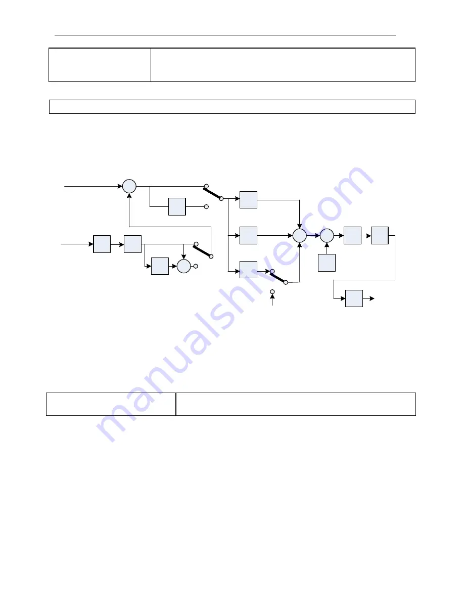
NOTE: The PID function is used for applications such as automatic flow control, external fan
volume control, air pressure control, and temperature control. See flow control diagram
below.
-1
PID
Output
Sleep
Mode
C38 / C39
Offset
Delay
C35 / C36
PID
Limit
Upper = F07
Lower = F08
C37
+ / -
+
+
C30 = 1,3
C30 = 2,4
0
C34
C33
C32
P
I
D
C30 = 1,2
C30 = 3,4
Forward
Reverse
C30 = 2,4
C30 = 1,3
+
-
F15 (AIN) = 18
PID Feedback
F05 Frequency
Command
(PID Command)
Signal
Gain
D
C31
F16 (AIN)
Signal
Select
+
+
C34
1.) In PID mode select, AIN on TM2 is the PID feedback signal (Set F15=018.)
2.) The PID command (set point) is selected by parameter F05 = ( 000, 001 or 004).
This value is stored in F28.
PID sleep mode requires setting all functions below:
C30=001
– 004 (PID Enable)
F15=018 (AIN is the PID feedback signal)
F28=PID preset frequency
C38 sleep start frequency: (Hz)
C39 PID sleep delay time: (Sec)
When the PID output frequency gets lower than the PID sleep start frequency (C38) for longer than
the time set by (C39), the inverter output will decelerate to zero speed (Sleep mode). When the PID
output frequency becomes higher than the sleep start frequency (C38), the inverter output
accelerates to PID output frequency (Wake mode). Refer to Fig. 11.14 on the next page.
C38 PID Sleep start frequency
C39 PID Sleep delay time (sec)
00.0 - 200Hz
00.0 - 25.5sec
Fig. 11.13 PID flow control diagram
Summary of Contents for EV INVERTER Series
Page 69: ......


