EV Inverter Operating Manual
___________________________________________________________________________
TECO
– Westinghouse Motor Company 5
L1(L)
PE
L3(N)
L2
1
9
3 4
2
5 6 7 8
10 11 12
100 – 120VAC 1Ø
or
200 – 240VAC 1Ø
200 – 240VAC 3Ø
or
380 – 480VAC 3Ø
INPUT POWER
Braking
Unit
+
-
COM
S4
S3
S2
S1
+24V
RA
RB
Multi function
Relay Output
(
NO Contact
)
Source
Common point
(SW1 = PNP)
Sink
Common point
(SW1 = NPN)
+10V
AIN / S7
COM
FM+
Ain Multi function
Analog input
- Set Speed
PID Feedback
or
IM
Multi function
Analog output
(0 – 10 Vdc)
NPN
PNP
V
SW1: Digital Signal Selection
(NPN
Sink
or PNP
Source
)
SW2 : Analog Control Selection
(V 0-10V; I 4-20 mA)
1
2
Connector 302
Option Plug – in Modules
Refer to Section 2
S7 Multi function
Digital input
I
NOTES:
1 - Digital inputs S1,S2,S3,S4, & S7 are
shown. Digital inputs
S5 & S6
are
provided with a plug-in option module
0V
P
N
T1 T2 T3 PE
Remove cover by squeezing
both sides and pulling up.
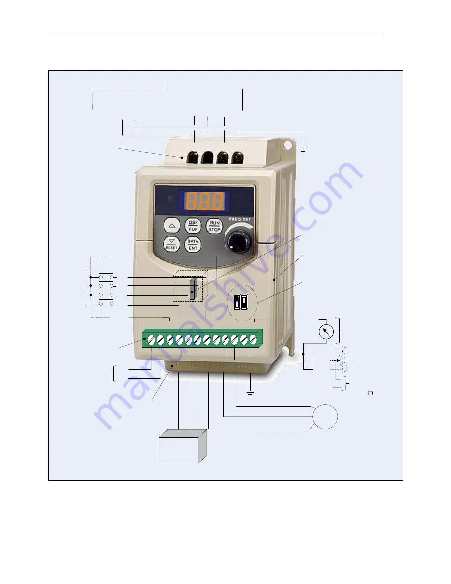
Fig. 1 EV Inverter Pictorial Wiring Diagram
Refer to Section 4 for additional
Input Power terminal
information
Refer to Section 5 for additional
Output Power terminal
information
Refer to Section 3 for additional
Control Signal terminal
information
(See Note 1))
Multi-functional
Digital Inputs
Summary of Contents for EV INVERTER Series
Page 69: ......


