EV Inverter Operating Manual
___________________________________________________________________________
TECO
– Westinghouse Motor Company 62
Appendix B
–
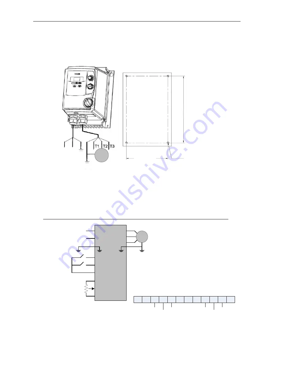
NEMA 4 EV Installation and Wiring
The following describes the installation and wiring for the
EV
inverter NEMA 4 enclosures.
Models: JNEV-1P2 / 1P5 / 101 / 2P2 / 2P5 / 201
– H1FN4S (IP65).
Notes:
1. Power switch, REV -0 FWD switch and
Potentiometer are only for for the models
JNEV – 1P2 to 201 – H1FN4S.
2. Power supply cable : #14 AWG (2.0m).
3. Motor cable: #16 AWG (1.25m)
4. Tightening torques:
- Power / motor cable plug-in terminal block (TM1):
4.34 lb-in.
- Control wiring terminal block (TM2): 3.47 lb-in.
- Outer cover screws (M4): 5.20 lb-in.
REV – 0 FWD
Switch
Potentiometer
L1
FWD
REV
+24V
0V
AIN
+10V
L2
(PE)
AC Input
100 – 120 VAC
Or
200 – 240 VAC
50 /60 Hz 1Ø
EV
3Ø
IM
(PE)
T1
T2
T3
1. Input source: 1Ø (L1, L2, PE) must be
connected to a 100 -120VAC or 200 -240VAC
supply.
2. Motor output: 3Ø (T1-T2-T3, PE).
CAUTION-
- Do not start or stop the drive using the main
input power.
- For the JNEV-1P2 to 201 -- H1FN4S type,
set the REV – 0 – FWD switch to 0 position
so that the drive has no run signal before
power- up. Otherwise injury may result.
L1 L2
100 – 120 VAC
50 / 60 Hz, 1Ø
(PE)
(PE)
123.4mm
19
8.
9m
m
4.86in.
7.
83
in
.
4-M4
Fig. B.1 JNEV NEMA4 Installation and Mounting
Foot Print
RA
RB
24V
S1
S2
S3
S4
COM
10V
AIN
COM
FM+
red
black
brown
orange
yellow
green
3Ø
IM
TM2
Fig. B.2 JNEV NEMA4 Wiring Diagram
Summary of Contents for EV INVERTER Series
Page 69: ......


