3-70
•
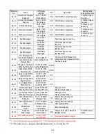
Different settings of Sn-35 and their corresponding multiple numbers as shown
below :
Sn-35 setting
Pulse output frequency
Applicable freq. range
0
1F
:
1 ×inverter output frequency
3.83
~
400.0Hz
1
6F
:
6 ×inverter output frequency
2.56
~
360.0Hz
2
10F
:
10 ×inverter output frequency
1.54
~
210.0Hz
3
12F
:
12 ×inverter output frequency
1.28
~
180.0Hz
4
36F
:
36 ×inverter output frequency
0.5
~
60.0Hz
(36)
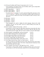
Inverter Station Address
(Sn-36)
(37)
RS-485 Communication Baud Rate Setting
(Sn-37)
(38)
RS-485 Communication Parity Setting
(Sn-38)
(39)
RS-485 Stopping Method After Communication Error (Sn-39)
•
The MA7200 inverter has a built-in RS-485 port for monitoring inverter status and
reading the parameter setting. Under the remote mode operation, the inverter status
and the parameter settings can be monitored. Moreover, the user can change the
parameters setting to control the motor operation.
•
MA7200 will use MODBUS protocol to communicate with external units by means
of the cable line form RS-485 port.
•
Parameter definition is as follows:
•
Sn-36 :
inverter station address, setting range 1~31.
•
Sn-37 = 0: 1200bps (bps: bit / sec)
= 1: 2400bps
= 2: 4800bps
= 3: 9600bps
•
Sn-38 = 0: no parity
= 1: even parity
= 2: odd parity
•
Sn-39 = 0: Deceleration to stop with Bn-02 (deceleration time), when RS-485
has communication error.
= 1: Coast to stop
= 2: Deceleration to stop with Bn-04 (deceleration time), when RS-485
has communication error.
= 3: Continue to run (will stop if the key stop is pressed)
•
Every data stream has a data length of 11 bits : 1 start bit
,
8 data bits
,
1 parity bit
and 1 stop bit. If Sn-38=0, the parity bit is 1.


