App-9
G.
S
ensorless Vector Control Set-up
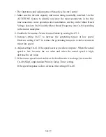
The MA7200 has two standard two selectable control modes, V/F Control Mode
(Sn-67=0) and Sensorless Vector Control Mode (Sn-67=1). When the Sensorless
Vector Control Mode is selected, be sure that the inverter capacity and the motor
rating are suitably matched.
The AUTOTUNE feature can be used to identify and store the important motor
parameters for the Sensorless Vector Control Mode.
Refer to pages
3-28, 3-29 and 3-73
for more details about Sensorless Vector
Control.
•
The Sequence of Motor Parameter Autotuning:
1. Disconnect the motor load and make sure that the wiring between the inverter
and the motor is suitable. The difference between inverter capacity and motor
rating should not be greater than two frame sizes.
2. Switch to PRGM operation mode by pressing the Digital Operator
PRGM
DRIVE
key.
3. Input the Motor Rated Voltage Data to parameter Cn-03 (Max. Output
Voltage) and the Motor Rated Frequency to parameter Cn-04 (Max. Voltage
Frequency) using data from motor’s nameplate. Enable Sensorless Vector
Control Mode (Sn-67= 1).
4. Enable the Autotuning Function by setting Sn-66= 1.
5. Switch to DRIVE operation mode by pressing the
PRGM
DRIVE
key, then run the
inverter by pressing the
RUN
key.
6. The inverter system immediately enters into the autotuning operation until
completing the autotuning procedure (normally about 25 seconds). The
inverter then returns to a stopped condition. Press the
STOP
key to stop the
parameter autotuning operation if an abnormality occurs during autotuning
operation.
7. Finally, press the
STOP
key to return the system to normal operation mode. The
value of motor parameter will be automatically stored in these parameters: Cn-57
(Motor Line-to-Line Resistance R1), Cn-58 (Motor Rotor Equivalent Resistance
R2), Cn-59 (Motor Leakage Inductance Ls) and Cn-60 (Mutual Inductance Lm).

