3-5
(5)
Analog Frequency Command Gain (Voltage) (Bn-05)
(6)
Analog Frequency Command Bias (Voltage) (Bn-06)
(7)
Analog Frequency Command Gain (Current) (Bn-07)
(8)
Analog Frequency Command Bias (Current) (Bn-08)
(9)
Multi-function Analog Input Gain
(Bn-09)
(10)
Multi-function Analog Input Bias
(Bn-10)
•
For every different analog frequency command (voltage or current) and multi-
function analog inputs, their corresponding gain and bias should be specified
respectively.
command value
Input voltage
(Input current)
* ( ) If current
command is used
0V
(4 mA)
10V
(20 mA)
Max. output
frequency
100
bias
Max. output
frequency
100
gain
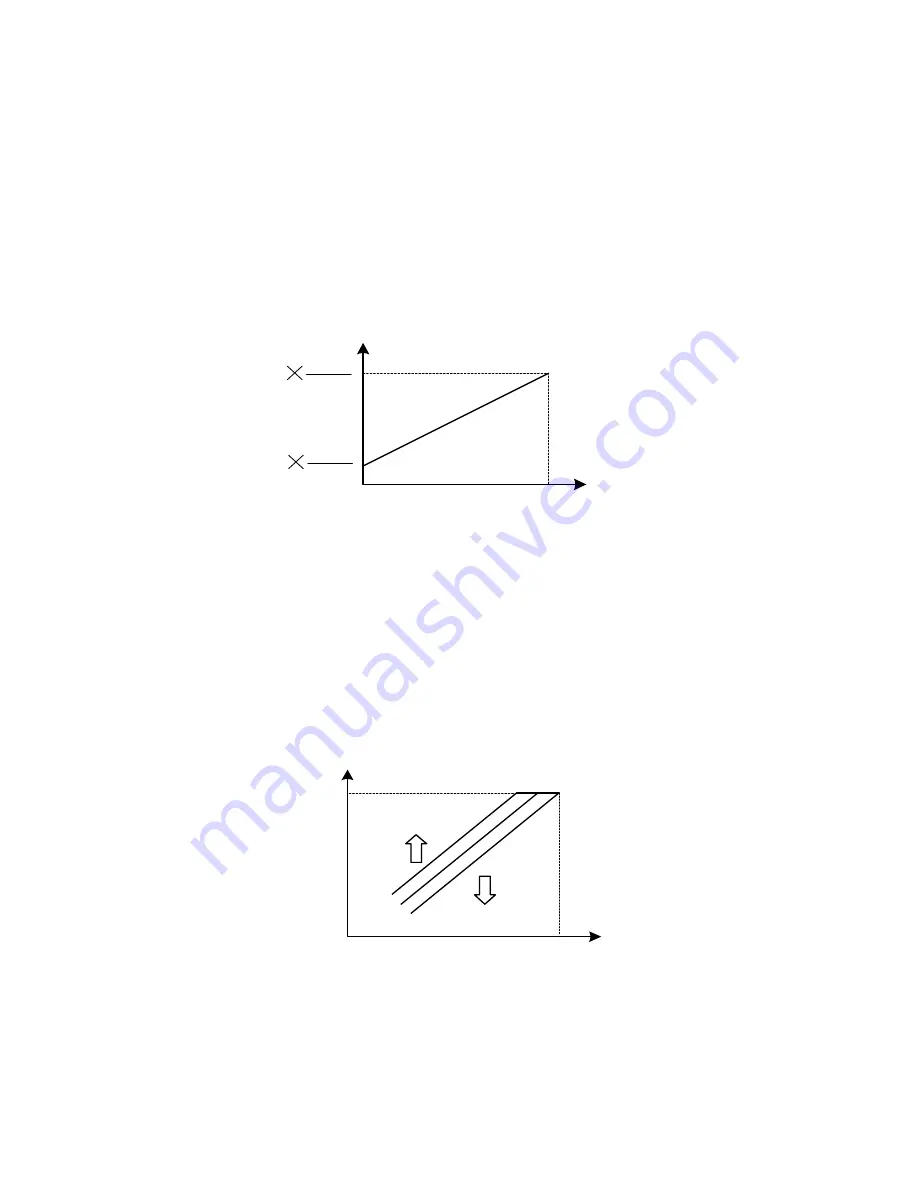
Fig. 10.
Analog input gain and bias
(11)
Auto Torque Boost Gain
(Bn-11)
•
The inverter can increase the output torque to compensate the load increase
automatically through the auto torque boost function. Then the output voltage will
increase. As a result, the fault trip cases can be decreased. The energy efficiency is
also improved. In the case that the wiring distance between the inverter and the
motor is too long (e.g. more than 100m), the motor torque is a little short because of
voltage drop. Increase the value of Bn-11 gradually and make sure the current will
not increase too much. Normally, no adjustment is required.
output
voltage
Base frequency
100 %
torque
increase
torque
decrease
Fig. 11.
Adjust the auto torque boost gain Bn-11 to increase the output torque.
•
If the driven motor capacity is less than the inverter capacity (Max. applicable
motor capacity), raise the setting.
•
If the motor generates excessive oscillation, lower the setting.


