background image

User’s manual

 - TECO 22 - 23 - 25 - 27 Special


21

Inflating tubeless tyres

(T.I. versions only) 

WARNING

Before carrying out the operations described below, always make sure that there is no dirt, 

dust or other impurities on the jaws near the air outlet holes.

- Make sure that the wheel is secured to the table top with inside clamping.

- Pull the horizontal arm all away out.

- Lower the vertical bar till it touches the rim.

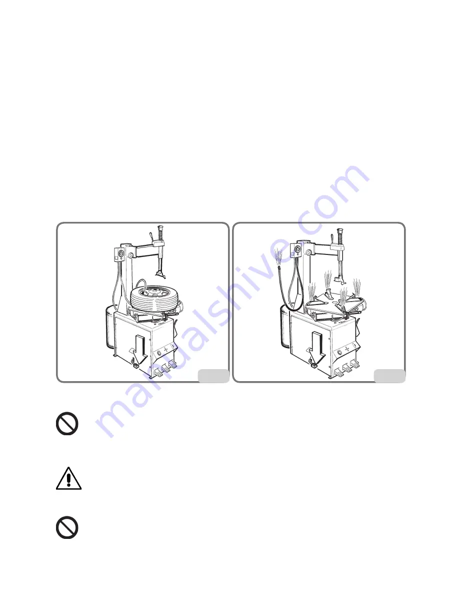
- Lock the horizontal and vertical arms in the positions described on Fig.20. 

- Connect the Doyfe inflator chuck on the air hose to the valve stem.

- Hold the tyre with your hands and lift it until there is a slight gap between the lower bead and bottom 

edge of the rim in order to close the upper bead and the top of the rim.

- Press the inflation pedal fully down for a short period to the bead seating position (fig.20). The tyre 

will expand and the beads will seat.

- Continue to press the pedal in the inflation position (fig.21) until the beads are completely sealed.

Note: to improve the operation of the tubeless tyre inflation system the compressed air line pressure 

must be between 8/10 bar.

MAINTENANCE


CAUTION

The “Spare parts” handbook does not authorize users to carry out work on the machine with the 

exception of those operations expressly described in the user manual. It only enables users to 

provide the technical assistance service with precise information in order to minimize delays.


WARNING

TECO declines all liability for claims deriving from the use of non-original spare parts or 

accessories.


CAUTION

Any operation intended to modify the setting value of the relief valves or pressure limiter is forbidden.

The manufacturer declines all liability for damage resulting from tampering with these valves.


20


21

Summary of Contents for 22

Page 1: ...Automotive Equipment Instruction Manual EN TYRE CHANGERS TECO 22 TECO 23 TECO 25 TECO 27 Special Version 2 2 April 2016 ...

Page 2: ...ronique de reproductionetd adaptationtotaleoupartielleparn importe quel moyen y compris microfilms et copies photostatiques sont réservés Les informations contenues dans ce manuel sont sujettes à des variations sans préavis Alle Rechte der Übersetzung elektronischen Speicherung Vervielfältigung und Teil oder Gesamtanpassung unter Verwendung von Mitteln jedwederArt einschließlich Mikrofilm und foto...

Page 3: ...0 MANUFACTURER S LABEL 10 TECHNICAL DATA 11 standard accessories 12 ACCESSORIES SUPPLIED ON DEMAND 12 SPECIFIED CONDITIONS OF USE 12 MAIN OPERATING PARTS 13 WARNING SIGNALS 15 PRACTICAL HINTS 16 usE 17 DEMONTAGE 18 MONTAGE 19 INFLATION 20 MAINTENANCE 21 ENVIRONMENTAL INFORMATION 24 INFORMATION AND WARNINGS ABOUT OIL 25 RECOMMENDED FIRE EXTINGUISHING DEVICES 26 GLOSSARY 27 TROUBLE SHOOTING 27 ELECT...

Page 4: ...or transferred to a new owner The manual is only to be considered valid for the model with the serial number indicated on the nameplate applied to it WARNING Observe the contents of this manual the producer declines all liability in the case of uses of the machine not specifically described and authorized in this manual WARNING This machine must be used only by qualified and authorized personnel A...

Page 5: ...kg TECO 25 208kg TECO 27 Sp 215kg Ambient conditions for machine transport and storage Temperature 25 55 C WARNING Do not stack other goods on top of the packing to avoid damaging it Handling To move the packing insert the tines of a fork lift truck into the slots on the base of the packing itself pallet fig 1 ATTENTION Carry out the moving operations with great care paying attention to move the p...

Page 6: ...rpose the not ched washers wihch allow the electric continuity of the machine Assemble the bead breaker with the proper pin and fasten it with the locknut until there is a slight resistance in the rotation of the bead breaker Connect the tank union to the air connection pipeline provided securing it with a band clamp Fix the air tank to the machine fig 1a T I version only HOISTING HANDLING To remo...

Page 7: ...m clearances shown in fig 3 adjust the height of the bead breaking support foot so that the machine is correctly posi tioned on the flooring Place the machine so that the plug socket combination is easily accessible The machine must be placed on a horizontal surface preferably concrete or tiled floor Do not install on unstable or damaged surfaces The surface on which the machine rests must withsta...

Page 8: ...eral wiring diagram in this manual In order to prevent the machine from being used by unauthorized personnel it is advisable to disconnect the power supply plug when the machine remains idle switched off for long periods WARNING A good grounding connection is essential for correct operation of the machine NEVER connect the earth wire to a gas or water pipe telephone line or any other unsuitable ob...

Page 9: ...uipment correctly and that they are adequately supervised Never leave nuts bolts tools or any other equipment on the tyre changer as they may become entrapped between moving parts Not touch power lines or the inside of electric motors or any other electrical equipment before making sure the power supply has been disconnected Read this manual carefully and learn how to use the machine correctly and...

Page 10: ...on standardized street wheels The machine is solidly constructed It operates with the wheel in a vertical position for bead breaking and horizontal for mounting and demounting tyres All machine movements are controlled by the operator by means of the pedals MANUFACTURER S LABEL Each machine carries a plate with its identification and some technical data As well as the manufacturer s details it ind...

Page 11: ...50Hz 2 8 4 4A 1 1 1 5 kW Weight Teco 22 150 kg Weight Teco 23 163 kg 178 kg t i Weight Teco 25 173 kg 188 kg t i Weight Teco 27 Sp 185 kg 200 kg t i Weight of electrical electronic components 11 5 kg Noise level A weighted sound pressure level LpA at the working position 70 dB A 3dB A The noise levels indicated correspond to emission levels and do not necessarily represent safe operating levels Al...

Page 12: ...n this manual WARNING Any other operation carried out on the machine is considered as improper use and shall be construed as negligence These machines are equipped with an inflation system independent from any other function described above Take great care when using it read the INFLATION chapter WARNING You are strongly advised not to use equipment or tools not originally manufactured by TECO Fig...

Page 13: ... the machine must be installed and operated correctly and serviced regularly The machine main operating parts are shown in fig 9 1 Reverse control pedal 2 Turntable 3 Bead breaker pedal 4 Bead breaker arm 5 Clamp control pedal 6 Clamp 7 Vertical arm 8 Horizontal arm 10 Mounting bar 11 Inflating gun with pressure gauge 12 Pressure regulator 13 Wheel support 14 Bead breaker 15 Grease container holde...

Page 14: ...14 User s manual TECO 22 23 25 27 Special 9 13 14 11 22 standard version 12 t i version tubeless inflating 18 10 16 6 2 7 4 17 3 5 1 8 15 21 19 20 23 ...

Page 15: ...ND RIM DANGER OF HAND CRUSHING BETWEEN MOUNTING HEAD AND WHEEL D CAUTION AIR BLAST MAX AIR SUPPLY LINE PRESSURE 16 BAR E INFLATING GUN CONNECTION DO NOT DIRECTLY CONNECT THE COMPRESSOR only on standard version CAUTION ELECTRIC CURRENT DANGER OF CRUSHING PARTS OF THE BODY BETWEEN THE BEAD BREAKER AND THE WHEEL DANGER OF CRUSHING PARTS OF THE BODY BETWEEN THE BEAD BREAKER ARM AND THE MACHINE A CAUTI...

Page 16: ...wheels Alloy rim wheels some wheels have alloy rims where the drop centre A is very small or non existent fig 10 B These rims are not approved by the DOT Department of Transportation standards these initials certify that tyres comply with the safety standards adopted by the United States and Canada these wheels cannot be sold in these markets DANGER Take utmost caution when mounting the tyre The r...

Page 17: ...uring bead breaking Repeat this operation on the other side of the wheel It may be necessary to break the bead at several points to free it completely WHEEL CLAMPING Check if there are any weights left on the rim if so remove them Thoroughly lubricate the sides of the tyre around the entire circumference of the lower and upper bead to facilitate the demounting and avoid damaging the beads fig 12 T...

Page 18: ...er between the mounting head and the tyre bead and lift the bead above the forward portion of the mounting head itself Make the turntable rotate clockwise by pressing the relevant pedal lightly and repeatedly then keep the pedal continuously pressed Rotate the wheel through one turn and at the same time press down with a hand on the side of the tyre opposite to the mounting head in order to positi...

Page 19: ...unting Also check that rims are not deformed that their fixing holes have not become oval that they are not scaled or rusty and that they do not have sharp burrs on the valve holes Check that the tyre is in good condition with no signs of damage Tyre preparation fig 18 Grease both the tyre beads Place the tyre on the rim Head positioning Set the mounting bar in work position NB The tool is already...

Page 20: ...eration It must be carried out in accordance with the instructions below Safety goggles with plain lenses and safety footwear must be worn CAUTION During this operation noise levels assessed at 85 dB A may occur Operators are advised to wear hearing protection devices DANGER Although the machine limits the pressure it does not provide sufficient protection if the tyre bursts during inflation Failu...

Page 21: ...l fully down for a short period to the bead seating position fig 20 The tyre will expand and the beads will seat Continue to press the pedal in the inflation position fig 21 until the beads are completely sealed Note to improve the operation of the tubeless tyre inflation system the compressed air line pressure must be between 8 10 bar MAINTENANCE CAUTION The Spareparts handbookdoesnotauthorizeuse...

Page 22: ... this equipment except in the case of service operations DANGER When the machine is disconnected from the air supply system the devices marked with the warning sign shown above may remain pressurised The filter regulator lubricator Teco 27 Sp is equipped with a semiautomatic condensation drain device This device operates automatically whenever the compressed air supply to the machine is cut off Dr...

Page 23: ...ing bar Disconnect the machine from the pneumatic circuit Remove cap 1 and let a few drops of non detergent SAE 20 in using an ampoule put cap 1 back on and tighten firmly Check the stretch of the motor reduction gear driving belt using the machine such belt may become loosen and worn out CAUTION Keep the working area clean Never use compressed air jets of water or solvent to remove dirt or deposi...

Page 24: ...r recycle and reuse many of the materials used in these products For this purpose the electrical and electronic equipment manufacturers and dealers set up proper collection and treatment systems for these products Attheendoflifeofyourproductcontactyourdealertohaveinformationonthecollectionarrangements When buying this new product your dealer will also inform you of the possibility to return free o...

Page 25: ...e end of every working shift do not smoke or eat with greasy hands Also adopt the following preventive and protective equipment gloves resistant to mineral oils with lining goggles in case of splashes aprons resistant to mineral oils screens to protect against oil splashes Mineral oil first aid procedures Swallowing seek medical attention providing the characteristics of the type of oil swallowed ...

Page 26: ...ss A tyre without an inner tube TROUBLE SHOOTING CAUTION In case of unexpected failure electrically insulate the machine by means of an omnipolar discon nection device Turntable not turning Feeding plug not connected or defective Check the plug Machine not powered Restore the electric connections Defective inverter Replace the inverter skilled staff needed in this case Motor shorted Replace the mo...

Page 27: ... table top makes 1 3 of a spin and then stops Gear unit seizing Replace gear unit Table top fails to clamp wheels Table top does not clamp rim Renew table top cylinder Table top mounts or demounts wheels with difficulty Insufficient belt tension Adjust tension or replace belt Tyre pressure gauge needle fails to return to 0 Pressure gauge faulty or damaged Replace pressure gauge WARNING The Spare p...

Page 28: ...arity Switch x 11 12 x 9 10 x 7 8 x 5 6 x 3 4 x 1 2 L 0 R 1 2 3 L1 ELEMENTI Elements CONTATTI Contacts W2 U1 U2 V2 V1 W1 W2 U1 U2 V2 V1 W1 200 220 240V 380 415 440V MORSETTIERA Junction Box F F F Power Phase 400V 3 50 Hz 0 55 kW 500V 4A 400V 3 50 Hz 0 75 kW 500V 6A 230V 3 50 Hz 0 55 kW 250V 10A 230V 3 50 Hz 0 75 kW 250V 10A 200V 3 50 Hz 0 75 kW Japan 250V 10A F Fuse ...

Page 29: ...TATORE DI POLARITA Reverse Polarity Switch x 11 12 x 9 10 x 7 8 x 5 6 x 3 4 x 1 2 L 0 R 1 2 3 ELEMENTI Elements CONTATTI Contacts F F Power Phase Neutral 230V 1 50 Hz 250V 16A 250V 16A 240V 1 50 Hz 250V 16A 250V 16A 220V 1 60 Hz 250V 16A 250V 16A 115V 1 60 Hz 250V 20A 250V 20A F Fuse W2 U1 U2 V2 V1 W1 C 8 12 3 2 MORSETTIERA Junction Box ...

Page 30: ...I Elements CONTATTI Contacts 1 3 5 7 9 11 2 4 6 8 10 12 13 15 17 19 21 23 14 16 18 20 22 24 L2 23 24 x x x 21 22 x 19 20 x 17 18 x x 15 16 x x 13 14 x 11 12 x 9 10 x 7 8 x x 5 6 x x 3 4 x 1 2 L2 L1 0 R 1 2 3 4 5 6 V2 U2 W2 W1 V1 U1 PE 22 13 15 24 9 11 F F F Power Phase 400V 3 50 Hz 500V 6A 230V 3 50 Hz 250V 16A 400V 3 60 Hz 500V 6A 230V 3 60 Hz 250V 12A F Fuse 28 ...

Page 31: ...D VALVE 07 CILINDRO STALLONATORE BEAD BREAKING CYLINDER 08 VALVOLA AUTOCENTRANTE SELF CENTERING CHUCK VALVE 09 RACCORDO GIREVOLE ROTATING UNION 10 CILINDRO AUTOCENTRANTE SELF CENTERING CHUCK CYLINDER 11 VALVOLA DI GONFIAGGIO INFLATING VALVE 12 VALVOLA A MEMBRANA VALVE 13 VALVOLA DI SICUREZZA SAFETY VALVE 14 UNITA DI GONFIAGGIO INFLATE UNION BOX 8 16 bar MAX 10 bar 01 02 03 04 05 06 07 08 09 10 10 ...

Page 32: ... LOWING DIRECTIVES EN ISO 12100 2010 EN 60204 1 2006 AC 2010 EN 61000 6 2 2005 AC 2005 EN 61000 6 3 2007 A1 2011 AC 2012 Correggio 01 04 2016 TECHNICAL DIRECTOR Ing Mauro Barbetti THE TECHNICAL DOSSIER RELATIVE TO CONSTRUCTION WILL BE kEPT AND WILL BE RENDERED AVAILABLE BY INg MAuRO BARBETTI C O TECO SRl VIA PIO lA TORRE 10 42015 CORREggIO RE ITAly IMPORTANT THIS DECLARATION SHALL NO LONGER APPLY ...

Page 33: ......

Page 34: ......

Page 35: ......

Page 36: ...Automotive Equipment Teco Srl Via Pio La Torre n 10 42015 Correggio RE Italy www teco it www tecorus ru www youtube com user TECOsrl Telephone 39 0522 631562 Fax 39 0522 642373 E mail teco teco it ...

Reviews: