3-12
3.6
Description of connection terminals
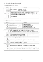
Descriptions of main circuit terminals
Symbol Description
TM1
L1
Main power input
Single-phase: L1/ L2
Three-phase:
L1/L2/L3
L2
L3
P
Braking resistor connection terminal: Used in applications
when it is required to stop a high inertia load rapidly. (refer
to specifications of the braking resistor)
220V:0.5~2HP,
380V:1~5HP
R
T1
Inverter outputs
T2
T3
Descriptions of
E310
control circuit terminals
Symbol
Description
TM2
RA
Normal open
contact
Multifunctional
output
terminals
Contact rated capacity:
(250VAC/1A or30VDC/1A)
Contact using description:
(refer to parameters 01-09, 01-10)
RB
Normal close
contact
RC Common
contact
10V
Frequency knob (VR) power source terminal (pin 3)
AVI
Analog frequency signal input terminal AVI (0~10VDC/2~10VDC)
ACI
PID signal input terminal or Bias signal input terminal ACI(0~20mA /4~20mA)
GND ground
SYN+ Positive terminal for multi-function output
30VDC/200mA
SYN- Negative terminal for multi-function output
TM3
COM Common for digital input signal for S1~S6 input.
S1
multifunction input terminals (refer to parameter 1-00~1-02 description)
S2
S3
COM Common for digital input signal for S1~S6 input.
S4
multifunction input terminals (refer to parameter 1-03~1-05 description)
S5
S6
FM+
The positive multifunction analog output signal for multifunction (refer to
parameter 2-12 description), the signal for output terminal is 0-10VDC (below
2mA).

