4-25
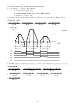
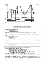
when the inverter is stopped. The keypad is available to modify the preset frequency (03-01). If
1-08=2, the UP/Down is available as the inverter stops.
2. 01-08=1 : as the Run terminal is energized, the inverter operates from 0 Hz, the Function of
UP/DOWN is same as the above description. When the Run signal is released, the inverter will
ramp stop or stop output (determined by 04-01) to 0 Hz. The next run command will always
begin from 0 Hz.
Multifunction output terminals control
:
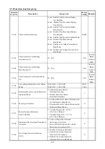
01-09 : Output Relay RY1 Operation Mode (RC,RB,RA terminal )
01-10 : Output Relay TR1 Operation Mode (SYN+, SYN- terminal)
0 : Run
1 : Fault
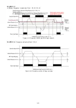
2 : Frequency Reached
3 : Set Frequency (01-11 ±01-12)
4 : Frequency Threshold Level (> 01-11) - Frequency Reached
5 : Frequency Threshold Level (< 01-11) - Frequency Reached
6 : Auto-restart
7 : Momentary AC Power Loss
8 : Emergency Stop Mode
9 : Base Block Stop Mode
10 : Motor Overload Protection
11 : Drive Overload Protection
12 : Over-torque Threshold Level
13 :Top Count Value Attained
14 :Preliminary Counter Value Attained
01-11 : Frequency Reached Output Setting =0.00 ~ 400.00Hz
01-12 : Frequency Detection Range =0.00 ~ 30.00Hz
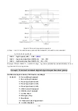
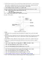
01-09/10= 2:
The preset frequency is reached (
01-12)
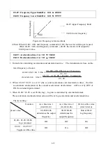
Figure 4-11Frequency reached example

